How to make a gearbox with an output shaft
1) Find a motor.
Well, lets start with a motor. Here are a few motors for me to
choose from. Choosing a motor that already has a gearbox is cheating,
so don't do it. I'v chosen to go with a dc motor for this gearbox, you
may choose a stepper if you like.
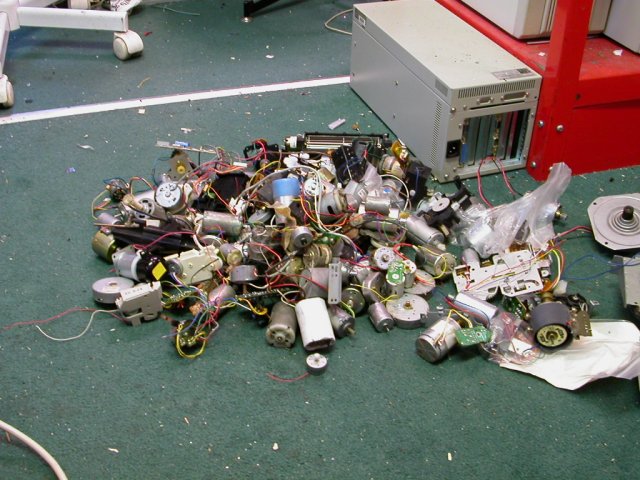
Fig 1.1 Available motors
ok well, maybe the first step should have been to vacumme the floor...
Anyhow, I have chosen a motor. Note that this motor already has a gear
on it, you may have to find a motor and a gear that match.
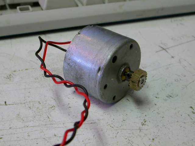
Fig 1.2 chosen motor.
2) Finding gears.
Here are a few gears for me to choose between. What we need to find is
a set of reduction gears that match the tooth spacing on the motor,
mind you only the first gear needs to match the motor, as long at the
gears you chain togethor mesh smoothly you ok.
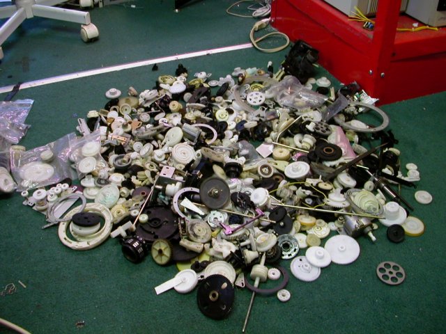
Fig 2.1 Gears to select form.
And here are the gears I have chosen. The last set of gears here are
really wide, this means I can put a fair bit of force on them without
them breaking.
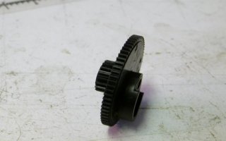
Fig 2.2 Gear to mesh with motor.
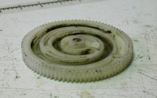
Fig 2.3 Output gear to mesh with previous.
3) Arrange the gears how you want them to be in the gearbox.
And here is how the layout will approximitly go.
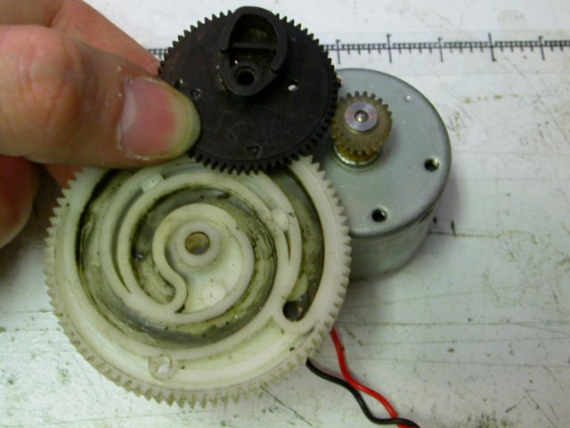
Fig 3.1 Gearbox layout.
As part of this, I'm going to cut off the cam on the gear that meshes with the motor.
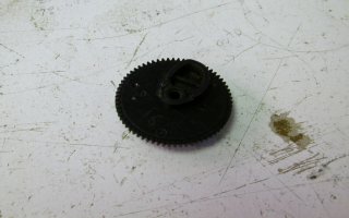
Fig 3.3 Gear with cam
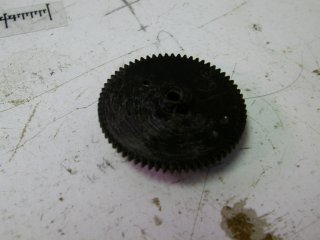
Fix3.4 Gear without cam
4) Material for the side plates.
Find two metal plates big enough to encompas all your gears with room
for putting screws through the box without hittings the gears
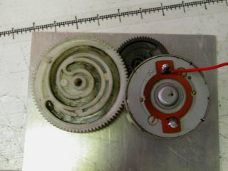
Fig 4.1 sizing of plate
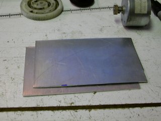
Fig 4.2 Two metal plates
5) Bolt plates togethor.
In the 'corners' of you plates, where there will be no gears, mark and
drill holes through the two plates big enough for machine screws, drill
them at the same time so they will be in the same place. Start with one
corner. Then put a bolt in that corner before drilling the next hole.
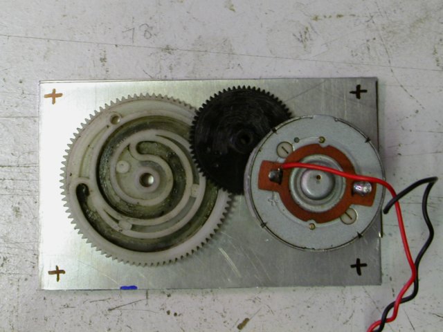
Fig 5.1 holes marked for corners
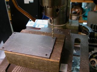
Fig 5.2 drilling plates at same time.
My machine screws are 6-32, so I use a 9/64" drillbit for my holes. After the first hole, do the opposite corner.
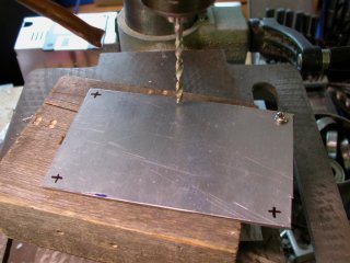
Fig 5.3 Drilling second hole with first hole bolted.
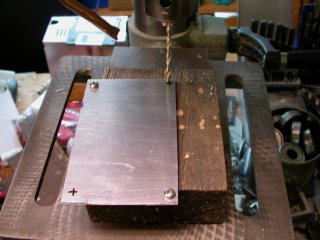
Fig 5.4 Drilling 3rd hole
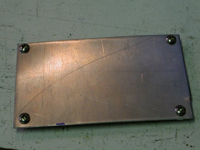
Fig 5.4 All holes drilled and bolted.
6) Gear Layout.
Place your gears on the plates so that they mesh just right and mark the middles of the gears REALLY carefully on the top plate.
I'm drawing a center line that I want the motor and output shaft to be
on. I find that a over extended mechanical pencil works well for
getting down the holes to mark where they are.
I'm able to take my gear off for doing this bit of layout, which helps
a little. Gears are really unfogiving out where they are put, so you
want them placed as accuratly as possible.
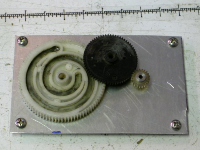
Fig 6.1 Laying out gear positions
7) Center punch holes.
Take off the gears, carefully centrepunch where the middle of the holes need to be.
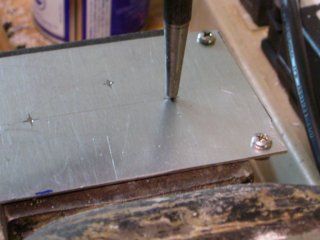
7.1 Center punched holes
8) Double check alignment.
Put the gears back on the plate, with the middles of them centered on the punch marks and check the alignment
Adjust the punch marks if needed and repeat the check till it all looks
good. Remember not to have the gears too tight or they will generate of
lot of resistance.
You can move a punched mark by hitting it with the punch just a little
bit off to the side and letting it slide into the origional mark.
10) Pilot drill holes.
Drill small holes on the punch marks, about 1/16" or 2mm
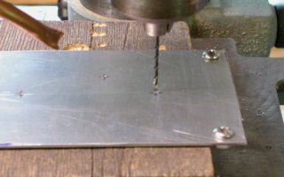
Fig 10.1 Drilling pilot holes.
11) Tripple check alignment.
Put the gears back on and check the alignment, mark the holes if any adjustments to the positions are needed.
12) Drill holes to size.
Drill the holes the size of the shafts you need for the gears. For the
motor, drill a hole big enough to fit the gear on the motor. the
location isn't critical for the motor, because its bolted to the
gearboxs side, you can move it around and adjust it.
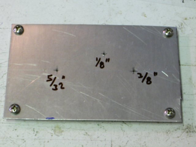
Fig 12.1 Hole sizes marked.
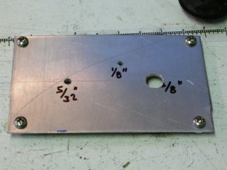
Fig 12.2 Holes drilled.
13) Unbolt the two plates.
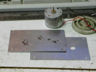
Fig 13.1 Plates unbolted.
14) Initial Assembly.
Take a sheet of paper and put it over the motor to get the hole pattern for bolting it down.
I like to take a mechanical pencil and push holes through the paper where the motors screws go.
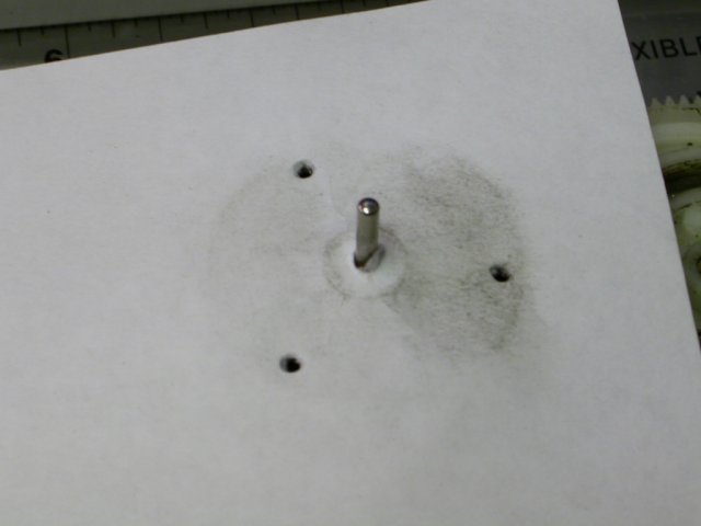
Fig 14.1 finding motor screw pattern.
Now take the sheet and put it on the plate, align the middle with the
hole in the plate and draw through the holes you made in the paper
where the screws were. Make sure the screws aren't somewhere that will
get in the way of the gears.
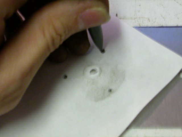
Fig 14.2 Transfering to metal plate
Drill the holes for the motor. If they don't quite end up in the right spot, you may be able ot make the hole a little bigger.
Bolt your motor in, be REALLY carefull that your screws aren't too long or they will wreck the motor.
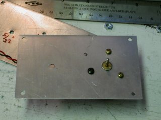
Fig 14.3 Motor bolted in.
Place the shafts through a side plate and put the gears on, put the top plate over that
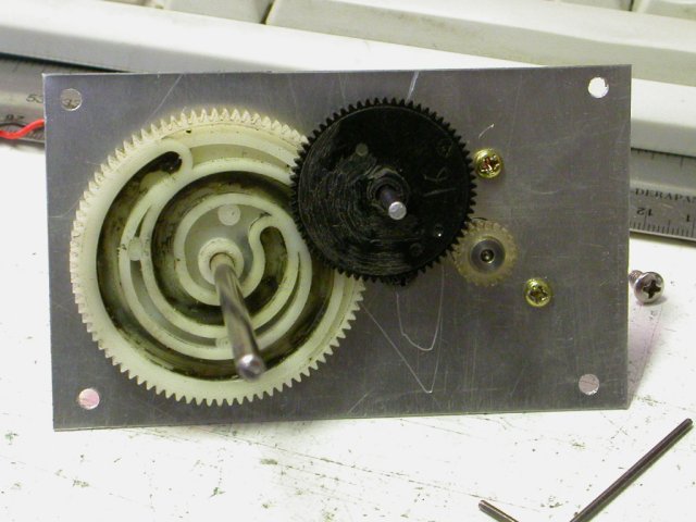
Fig 14.4 Shafts on, gears in.
15) Space Plates.
Put prethreaded rod through the corner holes and use nuts to space the
two plates the right distance apart. If your gearbox isn't too think
you can use long machine screws.
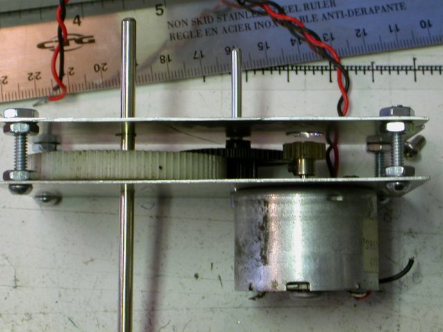
Fig 15.1 Plates bolted togethor.
16) Prepare shafts for installation.
Mark and cut the shafts (not the output shaft) for length based on the
width of the gearbox. Make sure both ends of the rod are flat and not
tapered.
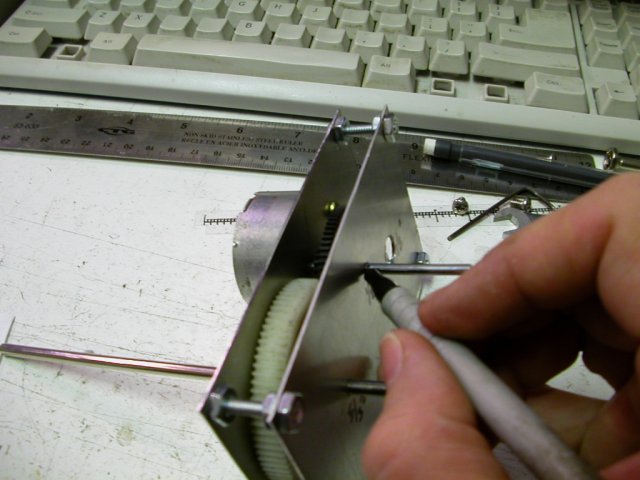
Fig 16.1 Marking pin length.
To cut the shaft, I use wire cutters, than file the end flat.
17) Make shaft retainers.
Make and attach plates that screw against the main plates over the shaft ends and hold them from slipping out..
This is basically just a little slip of metal to go over the shaft end
and hold it in. I marked some places I could put screws in the side
plate and drilled them. Then marked the holes on a small piece of plate
and drilled it.
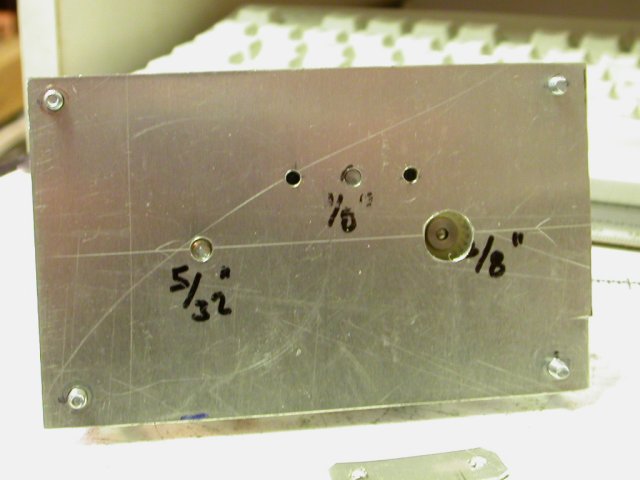
Fig 17.1 Holes drilled on either side of pin for retainer plate
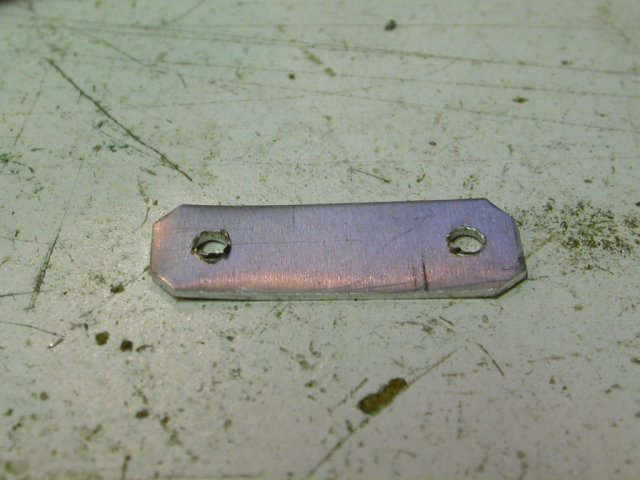
Fig 17.2 Retainer plate
Bolt in the retainer, I'm putting hte screw heads on the inside to make sure they dont get in the way.
Now we need one on the other side.
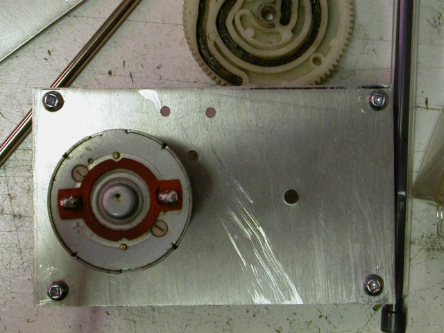
Fig17.4 Holes drilled for other plate.
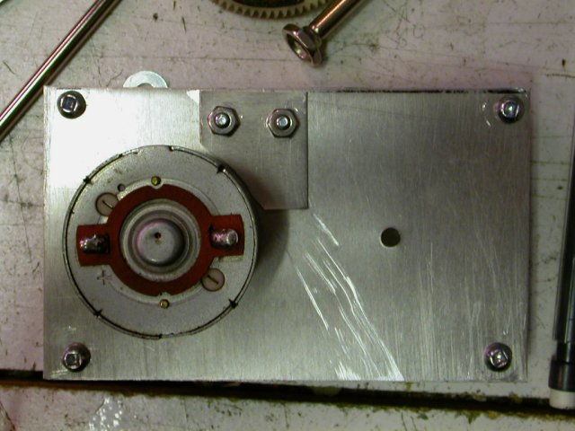
Fig17.5 Second plate Installed.
I don't suggest drilling holes with the gears in, its too easy to slip and wreck one.
That being said, I now re-assemble the gearbox
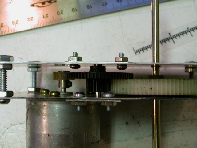
Fig 17.6 Gearbox reassembled with retainer plates.
18) Attach output shaft.
The last shaft in the gear train should go through the box. drill a
hole through the shaft and put a pin through it that sticks out both
sides. Cut a slot in the last gear that fits the pin. To keep the pin
in the slot, cut a groove for an E clip that will sit on the other side
of the gear.
Start by filing a small flat on the shaft. We will use that to help us
centerpunch it. Their hard to punch and you definitly need a vise. Try
to make sure not to squash the shaft in it, we need it to be round.
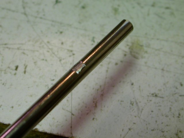
18.1 Flat on shaft.
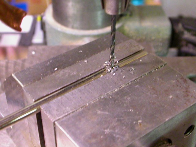
18.2 Drilling hole through shaft
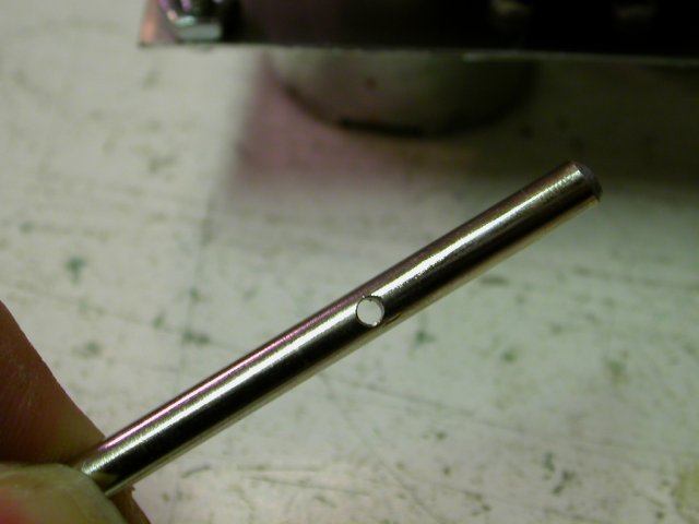
Fig 18.3 Hole drilled though shaft.
Put a pin through the shaft, you want it to be in really tight. You can
squash the pin a little with a hammer it its too loose. You could also
use a split or rolled pin. I'm able to make this pin quite long, you
shouldn't need a long pin, about a 1/4" should be just fine.
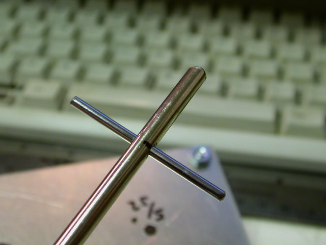
Fig 18.4 Pin in shaft
Next, Cut a slot in the gear for the pin.
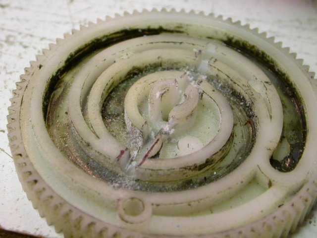
Fig 18.5 Slot for gear for pin
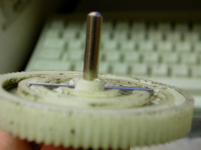
Fig 18.6 Test fit of pin in gear.
To keep the pin from slipping out, we put an E clip on the other side of the gear.
Mark the other side of the shaft from the pin and cut a ring for an E clip.
Be carefull of which way your gear goes on before you cut the ring.
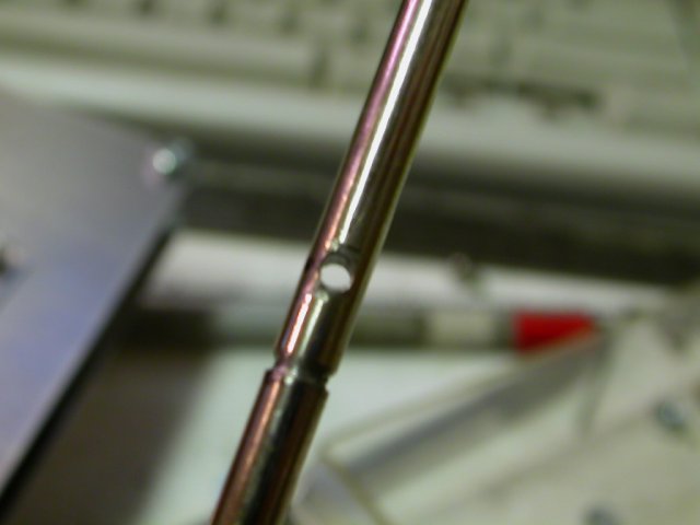
Fig 18.7 Groove for E clip
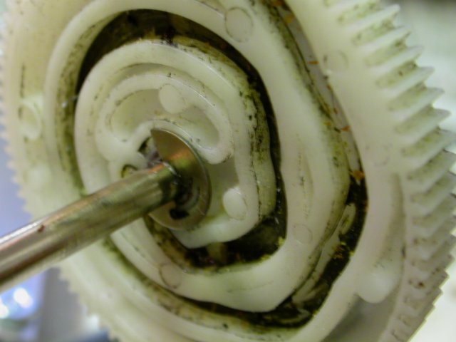
Fig 18.8 E clip on, gear securly attached to shaft.
Reassemble and thats it.
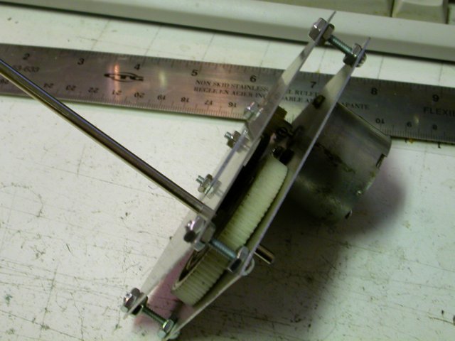
Fig 18.9 Competed Gearbox.
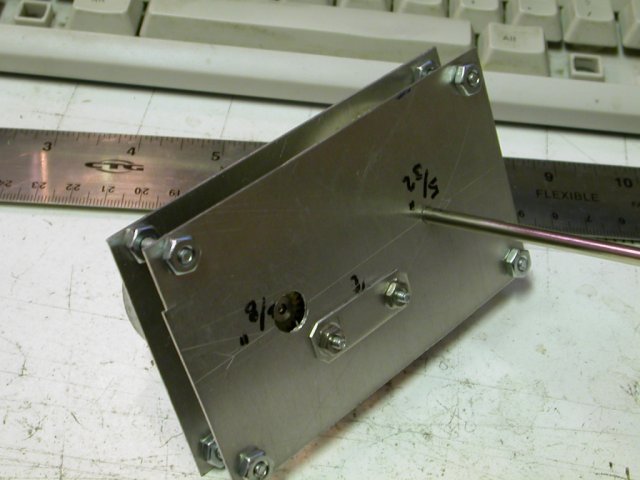
Fig 18.10
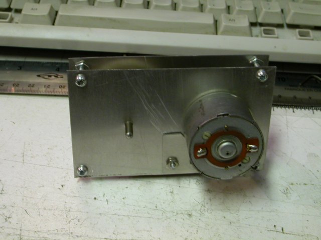
Fig 18.11
-- OOPS... --
In step 14.2ish, motor holes aren't quite in right palce, would have been good thing to doublecheck.
In step 18.7, the slots on the wrong side of the pin, made another slot on other side.