Next week, how to make a web page....
Oh yea, and were making it outa scrap parts...
oh and I'm really only gonna focus on making the inductor.
ok, because I need one now, were going to make a step up converter.
basic paramiters:
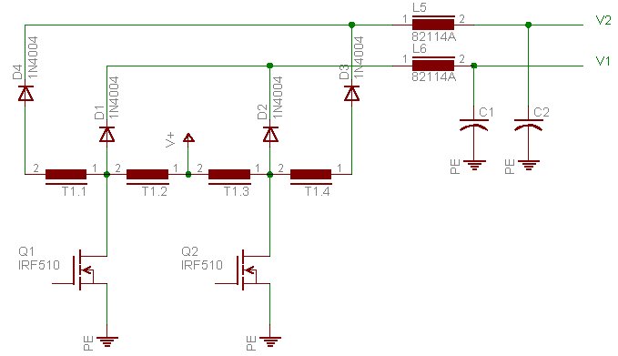
And here is the system were going to use:

V1 will be 2 x V+
V2 will be 4 x V+
so T1 needs to have 4 windings,
with windings 1 and 4 having twice as many turns as 2 and 3
with windings 2 and 3 having the same number of turns
To design the inductor we do the following:
1) Find a ferrite core,
if your using old ferrite transformers make sure they dont ahve a gap in the middle leg. Calculate the approximite corss sectional area of your core, in square meters.
2) getting your paramiters
you want to peak out your core at 200mT, because we dont know anything about it, this should be a safe number for just about anything. You need to calculate the number of turns for the primary. to do this, you need to know:
The formula to calculate turns is:
N = Vt/BA
where
N is the number of turns
V is the applied voltage
t is the "on" time
B is the flux density
and A is the area
Were going to run at 50% duty
____--------______--------_____--------______
so the on time for each "side" of the transformer is half our waveform period
t = (1/f)/2
where f is the frequincy ( Hz )
lets say we operate this at 50Khz, which is nicely above audioable
so
t = (1/50000)/2
t = 1e-5 seconds
the voltage across the winding that were driving is 6V
V = 6V
B = .2 tesla
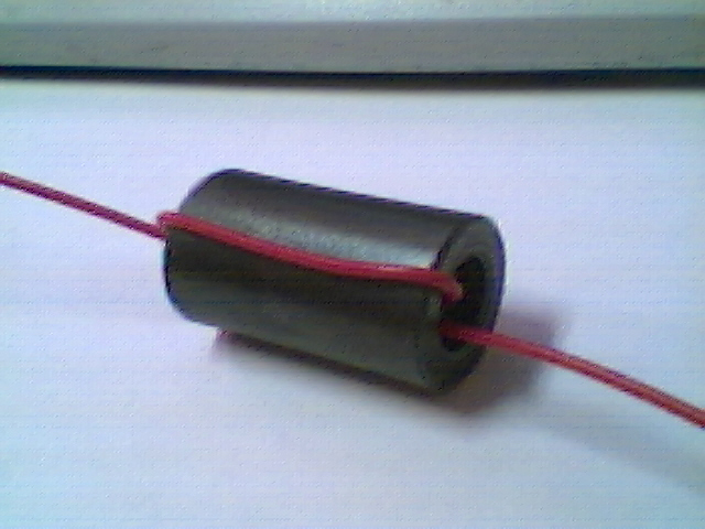
The area is based on the part of the core the wire circles:

On that one, its about 1.1e-4 m^2
so
A = 1.1e-4m^2
3) putting it all togethor
N = Vt/BA
V = 6V
t = 1e-5 seconds
B = .2 tesla
A = 1.1e-4m^2
N = 6*1e-5/0.2*1.1e-4
N = 2.7272727
more turns is better, so 3 turns for the 6V part
This means:
4) The oscillator
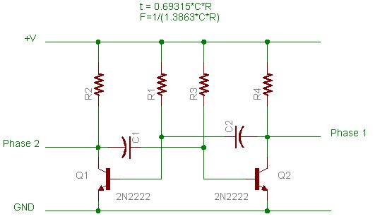
Here is the oscillator circuit, there are a few resons to use this particular circuit:
- it can produce 50% without hastle
- it will run on a large range of voltages

We already stated that f = 50Khz and that t = 1e-5 seconds.
The R in those formulas reffers to R1 and R3.
We need to choose a capacitor and resistor value.
I'll choose .01uF for C and see if we get a reasonable R
first some circuit re-arrangeing:
t = 0.69315*C*R
R = t/(0.69315*C)
and now some calculating...
R = 1e-5/(0.69315*1e-8)
R = 1442.6892
This is a resonable value, I'm going to round up to 1.5K which will decrease the frequincy, which will cuase the flux to be a little higher than we calculated for, but we used a large safety margin and this should be ok.
recalculating:
t = 0.69315*1e-8*1500
t = 1.04e-5
f = 48.076Khz
N = Vt/BA
NBA = Vt
B = Vt/NA
B = 6*1.04e-5/(3*1.1e-4)
B = 0.1891
Hey, were even lower than we wanted to max out at, sweet.
This would be because of the extra .383 turns we had to add
ask me to go through more details with you if you want. :)
dan
Oh yea, and were making it outa scrap parts...
oh and I'm really only gonna focus on making the inductor.
ok, because I need one now, were going to make a step up converter.
basic paramiters:
| Input voltage | 6V |
| Output voltage | 24V |
| Output current | 200mA |
And here is the system were going to use:

V1 will be 2 x V+
V2 will be 4 x V+
so T1 needs to have 4 windings,
with windings 1 and 4 having twice as many turns as 2 and 3
with windings 2 and 3 having the same number of turns
To design the inductor we do the following:
1) Find a ferrite core,
if your using old ferrite transformers make sure they dont ahve a gap in the middle leg. Calculate the approximite corss sectional area of your core, in square meters.
2) getting your paramiters
you want to peak out your core at 200mT, because we dont know anything about it, this should be a safe number for just about anything. You need to calculate the number of turns for the primary. to do this, you need to know:
- winding "on" time
- voltage across winding
- maximum flux density (200mT)
- core area(m^2)
The formula to calculate turns is:
N = Vt/BA
where
N is the number of turns
V is the applied voltage
t is the "on" time
B is the flux density
and A is the area
Were going to run at 50% duty
____--------______--------_____--------______
so the on time for each "side" of the transformer is half our waveform period
t = (1/f)/2
where f is the frequincy ( Hz )
lets say we operate this at 50Khz, which is nicely above audioable
so
t = (1/50000)/2
t = 1e-5 seconds
the voltage across the winding that were driving is 6V
V = 6V
B = .2 tesla
The area is based on the part of the core the wire circles:

On that one, its about 1.1e-4 m^2
so
A = 1.1e-4m^2
3) putting it all togethor
N = Vt/BA
V = 6V
t = 1e-5 seconds
B = .2 tesla
A = 1.1e-4m^2
N = 6*1e-5/0.2*1.1e-4
N = 2.7272727
more turns is better, so 3 turns for the 6V part
This means:
- winding 1 6 turns
- winding 2 3 turns
- winding 3 3 turns
- winding 4 6 turns
4) The oscillator
Here is the oscillator circuit, there are a few resons to use this particular circuit:
- it can produce 50% without hastle
- it will run on a large range of voltages

We already stated that f = 50Khz and that t = 1e-5 seconds.
The R in those formulas reffers to R1 and R3.
We need to choose a capacitor and resistor value.
I'll choose .01uF for C and see if we get a reasonable R
first some circuit re-arrangeing:
t = 0.69315*C*R
R = t/(0.69315*C)
and now some calculating...
R = 1e-5/(0.69315*1e-8)
R = 1442.6892
This is a resonable value, I'm going to round up to 1.5K which will decrease the frequincy, which will cuase the flux to be a little higher than we calculated for, but we used a large safety margin and this should be ok.
recalculating:
t = 0.69315*1e-8*1500
t = 1.04e-5
f = 48.076Khz
N = Vt/BA
NBA = Vt
B = Vt/NA
B = 6*1.04e-5/(3*1.1e-4)
B = 0.1891
Hey, were even lower than we wanted to max out at, sweet.
This would be because of the extra .383 turns we had to add
ask me to go through more details with you if you want. :)
dan