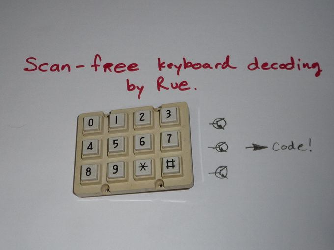
Scanless keyboard decoding
If your reading this, you likley are interested in a solution to identify keys from a keyboard made of an XY switch matrix. (I just thought you might want to know that, I suppose you might just like my drawings and have no interest in keyboards at all)
Welcome to scanless keyboard decoding, the idea is that, with a minimal amount of circuitry, you get a unique binary code from your keyboard for each key pressed. No resistors and ADCs, no scanning, no delays, just a unique code.
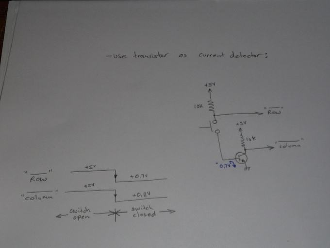
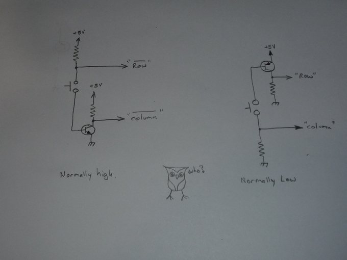
The core of the idea, is to use a transistor as a current detector. Two things happen when the button is pushed,
- The "row" is pulled down to "0.7V" by the BE junction of the transistor, and, due to that current flow,
- The collector of the transistor is pulled down. (0.2v? 0.7??)
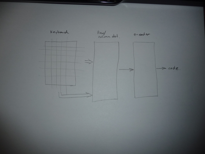
The system as a whole usually consists of 3 parts.
- The keyboard,
- The row/column detector,
- An encoder.
As a good person once said, you can skip any one part of a project, but skipping all of them with leave you with no project at all. (thanks Tony)
Here is an implementation with just a buffer chip:
The row / column detector can be one of two types*,
- Normally high output
- Normally low output
This option can help with the optional decoder that comes next.
* you can mix these too, and even have a row/column with no output, I'm not going there right now :)
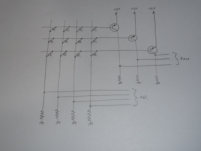
To expand this circuit past 1 row and 1 column, just duplicate the circuit per row/column, quick example:
*There are all sorts of wonderful optimizations I didn't do here.
ENCODERS:
So the row/column detectors have lots of signals, adding an encoder reduces them. The encoder can help remove parts from the row/column detector too, here, 74LS is used for its built in pullup resistors on the inputs. Here is 7->4 with an optimization:
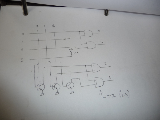
Here a few things are done.
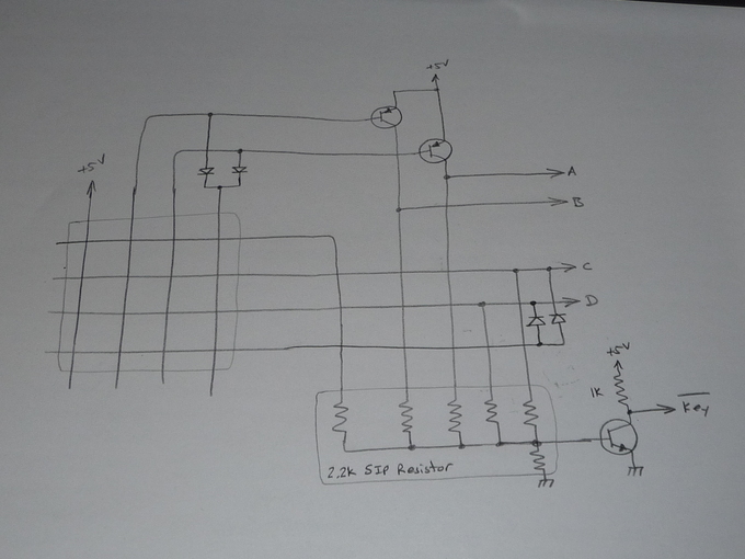
- The encoder is made of 4 diodes, substituted for transistors. (trust me just use
diodes)
- An additional transistor has been added as a "key down" detector.
- Row 0 / column 0 don't generate a signal, but the 'key down' will still trigger.
- An additional transistor has been added as a "key down" detector.
- Row 0 / column 0 don't generate a signal, but the 'key down' will still trigger.
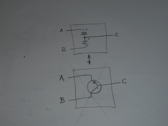
When is a transistor not a transistor?
When its two diodes. The general idea was to use a transistor instead of two diodes, but *sometimes* its trouble. Here is a redraw with diodes.
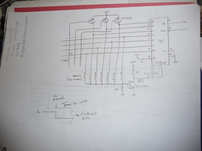
No decoder, I said optional right? Here, a shift register is used to grab the detector lines. Again, a "key down" circuit was added, monitor the serial line, it will go high when a key is pressed, then clock the value in!
Here, again, is an example of no decoder, The microcontroller is programmed with the pullups enabled on the input lines. Just read the value, no scanning!
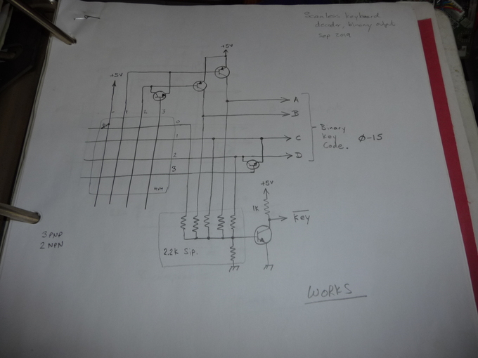
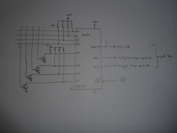
ROM decoder, this seems practical up to about an 8x9 matrix, after all, the encoding process is just a lookup table, right?
Here I'v shown with a 4x4 matrix, cause my pencil arm is getting tired. One of the advantages to this is 'key valid' signals are free. & uP interface!
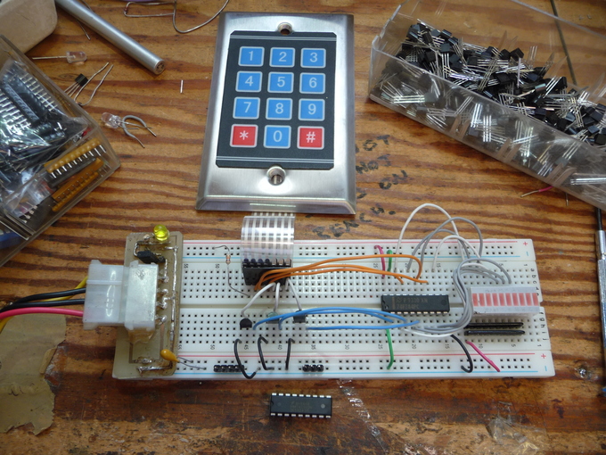
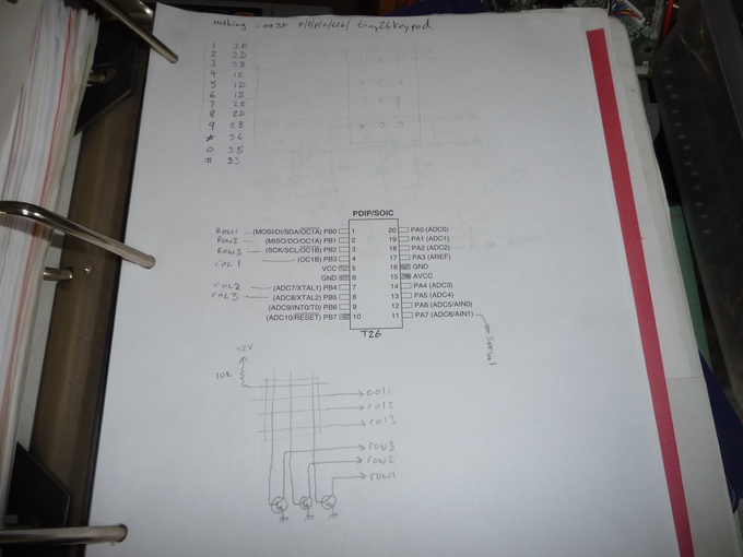
I need to use git more often!, anyhow, here is the code I used to generate the binary image for the 8x8 keyboard decoder I made yesterday! I made if from the new framework I'm using for LUTs and state machines.
https://github.com/ruenahcmohr/KeyBoardLUTGen
Please compute responsibly and recycle the bits used to render this page, this will help keep our internet healthy and ad-free.
Rue N. Mohr.