The "About" part of transistors (more crash course)
Transistors work by amplifying current,

B = Base
E = Emitter
C = Collector
There are 3 rules that you can use to figure out transistor circuits:
1) The current from the Base to the Emitter is multiplied by the
transistors gain, and up to that current flows between the Collector
and the Emitter.
Ib * hfe = Ic
2) There will be a voltage drop between the base and emitter of about .6 to .7 V
Vbe =~ 0.65V
3) The collector current is always the same (approx) as the emitter current
These rules are true for NPN and PNP transistors. The only difference is in teh direction that the currents flow.
On a NPN transistor, the arrow points away from the base, on a PNP transistor the arrow points to the base.
Now lets look at some transistor applications:

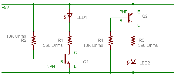
Here we have two examples of what are reffered to as common emtter
amplifiers. This means that the emitter is connected to a common power
rail.
In these circuits R2 and R4 supply the current to make the transistors
turn on. as you can see in the left example, current flows from +9V
through R2, from teh base to the emitter, to negitive.
This current allows a current to flow between the collector and
emitter, again in the left example that would go form +9V, though the
led, through R1, into the collector and out the base.
If you try the same thing on the right example, aside from it all being
upside down, you will find its the same. ( start with negitive and go
to positive)
-------------| ok enough class, time for some chit-chat |--------------
01:31:37: .......rue_more:can I give you my transistor crash course?
01:34:18: .........RifRaf:i just finished one
01:34:29: .......rue_more:tell me how they work
01:34:35: .........RifRaf:but sure if its a webpage show me
01:34:51: .......rue_more:na go it from memory
01:35:00: .......rue_more:just the basics
01:35:39: .........RifRaf:ok i think of a npn as a switch that needs a positive trigger, and a pnp as one that needs a negative type trigger
01:35:59: .......rue_more:RifRaf ok
01:38:29: .......rue_more:can I give you a little more rhym and reason to it all?
01:40:45: .........RifRaf:sure
01:42:32: .......rue_more:!assist elextut/comm_emit_amps.gif

01:44:44: .......rue_more:ok, want to start with NPN or PNP?
01:44:56: .........RifRaf:NPN
01:45:10: .......rue_more:ok, the following rules apply to both types of transistors
01:45:35: .......rue_more:1) to turn on, a current needs to flow from the base to the emitter
01:46:22: .......rue_more:2) the collector current is always the same (approx) as the emitter current
01:47:11: .......rue_more:3) the collector current = the (base-emitter) current * the transistors amlification factor
01:47:24: .......rue_more:thats it.
01:47:32: .......rue_more:say when ready
01:48:42: .........RifRaf:yep thats all clear
01:48:56: .......rue_more:ok so lets start with the npn side, on the left
01:49:19: .......rue_more:also to know, is that the base-emitter of a transistor is basically just a diode
01:50:17: .......rue_more:so
on that NPN side, you basically have a diode with (for a npn) its
negitive (the emitter) on ground, and its positive (the base) to R2
01:50:52: .......rue_more:current is going from +9 through R2, through the base-emitter diode of the transistor to ground
01:50:59: .......rue_more:ok?
01:53:14: .......rue_more:it works if you think of arrow on the transistor as a diode symbol...
01:55:01: .........RifRaf:yep thats clear
01:55:26: .......rue_more:ok, so because of the base-emitter current, the transistor is on
01:55:46: .........RifRaf:yep
01:55:56: .......rue_more:if I said the voltage drop across the base-emitter diode was 0.7V can you work out the current?
01:56:04: .......rue_more:I = V/R
01:57:08: .........RifRaf:.83mA
01:57:11: .......rue_more:yup
01:57:25: .......rue_more:ok, so lets say the transistors gain is 100
01:57:40: .......rue_more:in theory, whats the collector current?
01:57:55: .........RifRaf:83mA?
01:58:02: .......rue_more:yes
01:58:22: .......rue_more:now, what you have to realize about that, is that its the MAX possable collector current
01:58:47: .........RifRaf:k
01:59:00: .......rue_more:if you put it in a circuit with 1 ohm, the most drive you could get would be 83mA
01:59:49: .......rue_more:a transistor usually has about 0.2 to 1V (depending) between the collector and emitter when its fully "on"
02:00:04: .........RifRaf:k, so is not just a switch then, is a controlled switch
02:00:13: .......rue_more:its a current amplifier
02:00:21: .........RifRaf:yep
02:00:26: .......rue_more:if BE current = 0, CE current = 0
02:00:43: .......rue_more:so, with that, do you start to see how to PNP circuit works?
02:00:59: .........RifRaf:yeah
02:01:56: .......rue_more:so if you have a motor that pulls 250mA, and a transistor with a gain of 100, whats the min base current you technically need?
02:02:00: .........RifRaf:was mixed up a bit cause they draw the emitter on the other side but on the transistor the pinouts are the same
02:02:13: .........RifRaf:2.5mA
02:02:32: .......rue_more:yup, if thats being driven by 5V, what resistor do you need to use on the base?
R = V/I = 5/.25mA = 2000
02:03:28: .........RifRaf:2K
02:03:31: .......rue_more:yup
02:03:42: .......rue_more:so... your motor driver, whats your transistors gain?
02:03:44: .......rue_more:Hfe
02:03:54: .........RifRaf:will check
02:05:47: .........RifRaf:2n2222 = 100-300
02:05:56: .......rue_more:ok
02:06:05: .......rue_more:its always good to use worst case
02:06:05: .........RifRaf:2m2907 = 100 - 300\
02:06:29: .......rue_more:so with 5mA drive current, your good to how many amps?
02:06:49: .........RifRaf:.5
02:06:55: .........RifRaf:or 1.5A with the 300
02:07:12: .......rue_more:always use worst case, the lowest gain:)
02:07:35: .........RifRaf:100?
02:07:38: .......rue_more:yes
02:07:43: .........RifRaf:so 1/2 an amp
02:07:48: .......rue_more:then your safe
02:08:11: .......rue_more:now if you dont have enough base-emitter current, the transistor will not turn fully on
02:08:16: .........RifRaf:stall current was .5A
02:08:43: .......rue_more:which means that its dissipating voltage across it
02:08:53: .........RifRaf:cause the motor was slow and they got hot
02:09:10: .......rue_more:and if its carrying current AND dissipating voltage (as they always do) it generates heat
02:09:18: .......rue_more:P(heat) = I*V
02:09:26: .......rue_more:if the transistor is off, I = 0
02:09:37: .......rue_more:if the transistors fully on, V = ~0
02:09:53: .......rue_more:but if , say for 5V the transistor is half on
02:09:58: .......rue_more:V = 2.5
02:10:23: .......rue_more:say at a quarter the motor current which is .125A
02:10:26: .......rue_more:then we get
02:10:35: .......rue_more:.31W
02:10:47: .......rue_more:probably more than the transisotr can dissipate
02:11:00: .......rue_more:er go it gets hot
02:11:23: .......rue_more:thats why pwm goes from fully on to fully off, to aviod the middle bit where heat commes off
02:12:04: .........RifRaf:ok yep, do you think 1K may have not turned on the BC338 properly?
02:12:22: .........RifRaf:though seems like it should
02:12:50: .......rue_more:its
possable that the transistor was picking up stray signals that were
turning it on slightly, causing it to start having to dissipate power
02:12:52: .........RifRaf:.125A is 1/4 stall current, normal is just .05A
02:13:08: .........RifRaf:but they did blow when i tried to stall the motor once
02:13:25: .......rue_more:its possable they just couldn't take it
02:13:36: .......rue_more:the 2n2222 is rated to 600mA
02:13:42: .........RifRaf:yep, but at least these work well now
02:14:31: .......rue_more: what happens if you use the NPN circuit without a resistor?
02:14:35: .......rue_more:on the base
02:15:34: .........RifRaf:you won't be limiting the current?
02:16:01: .......rue_more:so it blows up?
02:16:18: .........RifRaf:yep blows up without a resistor on the base
02:16:37: .......rue_more:because its just a diode across the power supply
02:16:44: .........RifRaf:short
02:16:48: .......rue_more:yup
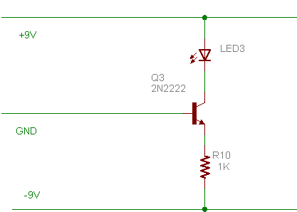
02:21:22: .......rue_more:ok, this is a strange circuit, relies on different rules
02:21:39: .......rue_more:!assist elextut/commonbase.gif

02:22:01: .......rue_more:my question to you is, what is the current through the led?
02:26:14: .......rue_more:always start with the base-emitter current
02:26:22: .........RifRaf:wat colour is the led?
02:26:42: .......rue_more:purple
02:26:43: .........RifRaf:looks red so lets assume 2V drop eh
02:26:52: .........RifRaf:no its not purple
02:26:55: .......rue_more:voltage drop dosn't matter for that though
02:27:06: .......rue_more:follow the 3 rules
02:27:14: .........RifRaf: ok
02:28:36: .......rue_more:take some guesses at how to approach it
02:29:04: .........RifRaf:ok so is BE current 9mA?
02:29:10: .......rue_more:yes
02:29:15: .......rue_more:well thre abouts
02:29:20: .......rue_more:the BEdrops 0.7V
02:29:29: .........RifRaf:so gain off 100 means 900mA possible through transistor
02:29:45: .......rue_more:yes
02:30:08: .......rue_more:but, its uses a rule that didn't apply last time
02:30:11: .........RifRaf:at 18V
02:30:29: .......rue_more:go back to the 9mA base current
02:30:58: .........RifRaf:ok so is BE current 9mA
02:31:02: .......rue_more:yes
02:31:13: .........RifRaf:then we work out the current with the hfe
02:31:20: .......rue_more:nope
02:31:27: .........RifRaf:that can go from CE
02:31:32: .......rue_more:nope
02:31:33: .........RifRaf:ok lets go back again
02:31:38: .........RifRaf:let me find the rules
02:32:21: .........RifRaf:ok so i am stuck then if i cannot move onto the CE current
02:32:34: .......rue_more:you can
02:32:49: .......rue_more:using a differnt rule
02:33:53: .......rue_more:how did you get the base current.
02:34:20: .........RifRaf:dividing the input voltage by the resistance
02:34:32: .......rue_more:right, so whats the current throught the resisitor?
02:35:03: .......rue_more:forget the collector
02:35:14: .........RifRaf:ok 9ma
02:35:19: .......rue_more:right
02:35:27: .......rue_more:so whats the emitter current?
02:35:46: .........RifRaf:the same?
02:35:50: .......rue_more:yup
02:36:40: .......rue_more:so whats the collector current?
02:36:55: .........RifRaf:900mA
02:37:16: .........RifRaf:but it won't be cause of the resistor
02:37:18: .......rue_more:nope
02:37:25: .......rue_more:the rules
02:37:34: .......rue_more:something relating the emitter and collector currents
02:37:45: .........RifRaf:2) the collector current is always the same (approx) as the emitter current
02:37:51: .......rue_more:yup
02:37:52: .........RifRaf:so 9mA?
02:37:56: .......rue_more:yup
02:38:09: .........RifRaf:mm
02:38:17: .......rue_more:hurts the brain eh?
02:38:37: .........RifRaf:yep a little
02:38:43: .........RifRaf:and i even have a clear head today
02:39:27: .......rue_more:you can put more leds inseries , and its still 9mA
02:39:37: .......rue_more:until there is no more voltage left
02:39:44: .........RifRaf:so thats the answer?
02:39:49: .......rue_more:yup
02:39:54: .........RifRaf:mm
02:40:09: .......rue_more:so if the lower rail was only -5V
02:40:13: .........RifRaf:ok you are right, it is a strange example
02:40:17: .......rue_more:what would the led current be?
02:40:31: .........RifRaf:9mA?
02:40:36: .......rue_more:nope
02:40:39: .........RifRaf:ok you changed it
02:40:56: .........RifRaf:5mA
02:41:01: .......rue_more:yes
02:41:40: .......rue_more:you can have a 5V led in there, you still get the same current
02:42:14: .......rue_more:RifRaf its called a common base amplifier
02:42:59: .......rue_more:common emmitter is the mose popular, then common collector, then common base
02:43:23: .......rue_more:they use common base for controlling the high voltage video signals on CRT;s
02:43:48: .......rue_more:ok, common collector and I give you a break!?
02:43:59: .........RifRaf:k
02:54:58: .......rue_more:!assist elextut/common_collector.gif

02:56:18: .......rue_more:soo here is the question for you
02:56:37: .......rue_more:what is the voltage on the output (top of R12)
02:57:13: .........RifRaf:5V at 5mA?
02:57:23: .......rue_more:1 ohm
02:57:31: .........RifRaf:woops
02:57:38: .........RifRaf:thought it was 1000
02:57:43: .......rue_more:nope
02:57:44: .........RifRaf:you are trying to trick me
02:57:49: .......rue_more:your right though its 5V
02:57:55: .......rue_more:thats the answer
02:57:55: .........RifRaf:5V 5A?
02:58:03: .........RifRaf:ah goodie :)
02:58:06: .......rue_more:so whats the base current if the gain is 200
02:58:15: .......rue_more:(its really 50)
02:58:57: .........RifRaf:25mA
02:59:02: .......rue_more:yes :)
02:59:15: .......rue_more:whats the current through r12?
02:59:47: .........RifRaf:5.025A
03:00:03: .......rue_more:by jove, I think he's got it
03:00:13: .........RifRaf:damn why did i say that last bit
03:00:24: .......rue_more:here is a really good one
03:01:14: .......rue_more:if
the top of R12 is at 5V, and the toppower rail is 24V, and the R12
current is ~5A what is the power dissipation of the 2n3055?
03:02:22: .......rue_more:so whats the power less on the 3055 RifRaf?
03:03:41: .........RifRaf:rue my brain is telling me to stop
03:04:07: .........RifRaf:now i know why you explode every day
03:04:50: .......rue_more:P = I * V
03:04:54: .......katsmeow:figure votage across the 3055
03:05:03: .......rue_more:wehre I is the current through it and V is the voltage across it
03:05:12: .......katsmeow:24 - 5
03:05:18: .........RifRaf:yeah i was just gonna say 5 x 24 but seems too easy
03:05:31: .......katsmeow:and the current thru the reistor is the same roughly as thru the transistor
03:05:39: .......katsmeow:(ignoring base drive)
03:06:04: .......rue_more:RifRaf its generally thought of as ok to ignore the base current as its "small"
03:08:38: .......rue_more:in the above example you can think of the transistor like a resistor
03:08:49: .......rue_more:from the collector to the emitter
03:09:15: .......rue_more:for power dissipation stuff


