/*******************************************************************************
Rue's "is it alive"
program for avr processors
also makes a good skel to
build your programs form ;)
16Mhz
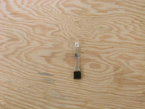
Red LED with clear lens.
*******************************************************************************/
/*
1 PB0
<- led
2 PB1
3 PB2
<- led
4 PB3
5 PB4
6 PB5
7 PB6
8 PB7
9 PA0
10 PA1
11 PA2
12 PA3
13
PA4
14 PA5
15
PA6
16 PA7
17 PC7
18 PC6
19 PC5
20 PC4
21 PC3
22 PC2
23 PC1
24 PC0
25 PD7
26 PD2
27 PD3
28 PD4
29 PD5
30 PD6
This example shows one way
of using an LED as a light sensor.
You will need to wire it
up like this:
+ port B0
|
<
> 470 ohm resistor
<
|
|
-----
/ \ 5mm red led with a clear lens
-----
|
|
+ port B2
What we are going to do is
apply a positive voltage at port B0 and
a low voltage at port B2.
This is backwards for the LED, current will
not flow and it will not
light, but we will charge up the
capacitance of the LED
junction.
Then we are going to
disconnect the output drivers from PORT B0 and
count how long it takes to
discharge. The brighter the light, the
lower the capacitance and
the faster is will lose its charge.
The rest of this app here
will watch the led and toggle its on/off state
when it sees a 'dark
happen' :)
*/
#include <avr/io.h>
// misc
#define SetBit(BIT,
PORT) PORT |= (1<<BIT)
#define ClearBit(BIT,
PORT) PORT &= ~(1<<BIT)
#define IsHigh(BIT,
PORT) (PORT & (1<<BIT))
!= 0
#define IsLow(BIT,
PORT) (PORT &
(1<<BIT)) == 0
#define
NOP()
asm volatile ("nop"::)
#define
OUTPUT
1
#define
INPUT
0
#define
HIGH
1
#define
LOW
0
#define
LED_CATHODE 2
#define
LED_ANODE 0
#define
LED_PORT
PORTB
#define
LED_DDR
DDRB
#define
LED_INPUT PINB
// this determines a 'light
level cutoff' if it sees less than 3000 units
// it gives up. this mixes with
the contrast delay you will read about later
#define
JMAX
3000
void Delay(int delay);
void Delay2(int delay);
int readLED( char onoff );
int main (void) {
unsigned int val;
char oncount, onoff;
// set up directions
DDRA = (INPUT <<
PA0 | INPUT << PA1 |INPUT << PA2 |INPUT << PA3 |INPUT
<< PA4 |INPUT << PA5 |INPUT << PA6 |INPUT <<
PA7);
DDRB = (OUTPUT <<
PB0 | OUTPUT << PB1 |OUTPUT << PB2 |OUTPUT << PB3
|OUTPUT << PB4 |OUTPUT << PB5 |OUTPUT << PB6 |OUTPUT
<< PB7);
DDRC = (INPUT <<
PC0 | INPUT << PC1 |INPUT << PC2 |INPUT << PC3 |INPUT
<< PC4 |INPUT << PC5 |INPUT << PC6 |INPUT <<
PC7);
DDRD = (INPUT <<
PD0 | INPUT << PD1 |INPUT << PD2 |INPUT << PD3 |INPUT
<< PD4 |INPUT << PD5 |INPUT << PD6 |INPUT <<
PD7);
onoff = 0;
oncount = 0;
val
= 0;
while (1) {
if (val <
600) // light level for us to decide to switch, depends on
contrast delay
oncount++;
else
oncount
= 0;
// 4 counts before
we toggle
if (oncount == 2) {
if
(onoff) onoff = 0;
else onoff = 1;
}
val =
readLED(onoff);
// leave it like
that for a bit before we do the next reading.
Delay(15000);
}
}
void Delay(int delay) {
int x;
for (x = delay; x != 0;
x--) {
asm volatile
("nop"::);
}
}
void Delay2(int delay) {
int x;
for (x = delay; x != 0;
x--) {
Delay(65000);
}
}
int readLED(char onoff) {
unsigned int j;
// Apply reverse voltage,
charge up the pin and led capacitance
SetBit(LED_CATHODE,
LED_DDR ); // OUTPUT
SetBit(LED_ANODE, LED_DDR ); // OUTPUT
SetBit(LED_CATHODE,
LED_PORT); // HIGH
ClearBit(LED_ANODE,
LED_PORT); // LOW
Delay(5);
// Isolate the cathode of
the LED
ClearBit(LED_CATHODE,
LED_DDR); // INPUT
ClearBit(LED_CATHODE,
LED_PORT); // turn off internal pull-up resistor
// Count how long it
takes the led to discharge to a logic zero
// this can take almost
like 1/4 second!
// In the
dark j is lower and takes longer.
for ( j = JMAX; ((j)
&& (IsHigh(LED_CATHODE, LED_INPUT))); j--) Delay(45); // this
delay controls contrast
// leave the led on if
they wanted it like that
if (onoff != 0) {
SetBit(LED_ANODE, LED_PORT); // anode high
ClearBit(LED_CATHODE, LED_PORT); // cathode low
SetBit(LED_ANODE, LED_DDR); //
output
SetBit(LED_CATHODE, LED_DDR); // output
}
// return the brightness
value
return j;
}
// find me if you want to know
how to read 8 leds with 9 io pins. :)
|