


|
|
|
|
555 LED Flasher |
|
|
|
|
|
|
|
|||||||||
|
Here is how to assemble a flashing
led on a breadboard. This is a good thing for getting used to
breadboards and assembling circuits and all that stuff. You will need the following parts:
---=Let the chaos begin =--- |
|
|||||||||
|
|
|
|
|
|
|
01)
Find some space for your
breadboard. Put it horizontally with the red stripe (if you have one)
at the top. (unlike this picture) This is the circuit were gonna build 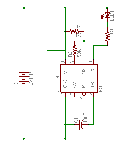 |
|
|
|
|
|
|
|
|
02)
Insert the LM555 with pin 1 to the right. Pin 1 is the pin with the dot beside it. 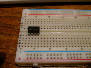 |
|
|
|
|
|
|
|
|
03)
Insert wire from pin 1 to ground. 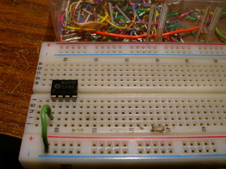 |
|
|
|
|
|
|
|
|
04)
Insert wire from pin 8 to positive  |
|
|
|
|
|
|
|
|
05)
Insert wire from pin 2 to pin 6. 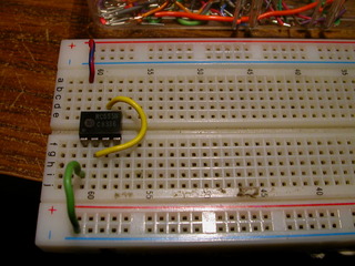 |
|
|
|
|
|
|
|
|
06)
Insert wire from pin 4 to pin 8.  |
|
|
|
|
|
|
|
|
07)
Insert a 1k resistor between pins 7 and 8, this is a 20 ohm resistor, oops... 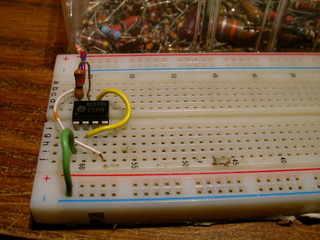 |
|
|
|
|
|
|
|
|
08)
Insert a 68K resistor between pins 6 and 7. 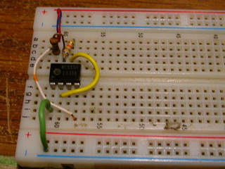 |
|
|
|
|
|
|
|
|
09)
Insert the 10uF capacitor between pins 1 and 2, make sure the - side is on pin 1. 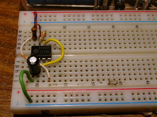  |
|
|
|
|
|
|
|
|
10)
Insert a 1K resistor from pin3 rightwards, this one is 470 ohms, oops...  |
|
|
|
|
|
|
|
|
11)
Insert the LED with the negitive side on the resistor. 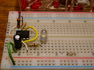 You can usually tell the polarity by what I call 'Anvil' (negitive side, 'cathode') and 'Post' (positive side, 'anode'), in this pic, you can see the anvil on the left and the post on the right.  |
|
|
|
|
|
|
|
|
12)
Insert wire from the anode of the led to positive.  |
|
|
|
|
|
|
|
|
13)
Insert the LM555 with pin 1 to the right. Pin 1 is the pin with the dot beside it. p |
|
|
|
|
|
|
|
|
14)
Insert the LM555 with pin 1 to the right. Pin 1 is the pin with the dot beside it. p |
|
|
|
|
|
|
|
|
15)
Insert the LM555 with pin 1 to the right. Pin 1 is the pin with the dot beside it. p |
|
|
|
|
|
|
|
|
16)
Insert the LM555 with pin 1 to the right. Pin 1 is the pin with the dot beside it. p |
|
|
|
|
|
|
|
|
17)
Insert the LM555 with pin 1 to the right. Pin 1 is the pin with the dot beside it. p |
|
|
|
|