Heard of an LVDT?
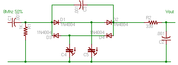
well this isn't one, its a nifty circuit I hacked off of
someone elses
page., here is some documentation for it.
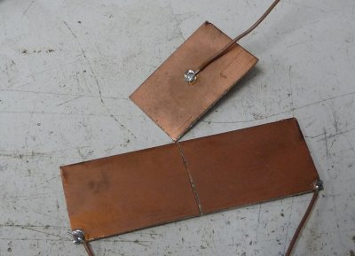
These are the sensor parts
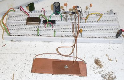
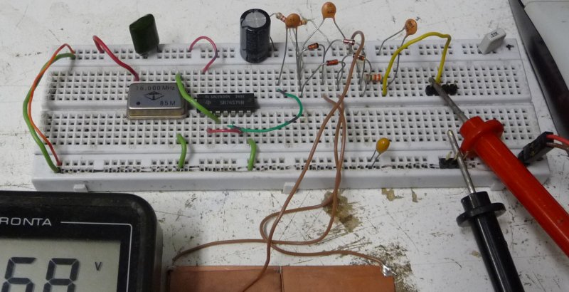
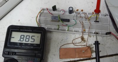
This is my implementation of the circuit
Measurements
as it stands
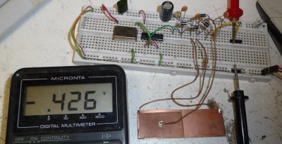
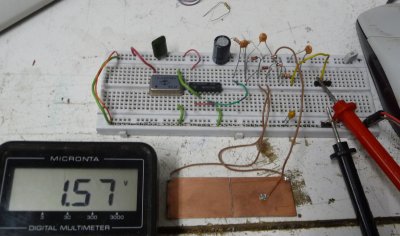
Full left deflection.
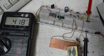
Full right deflection.
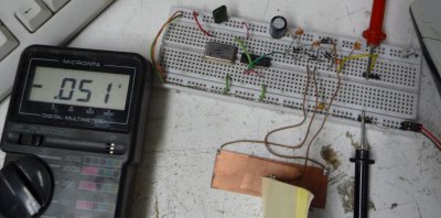
Almost full middle deflectionisity.
Sorry, the wires were springy and I had to hold it down with a postit
pad.
Now
to mess with it
Now some mods, I replaced the 1N4004
with 1N4148, which are lower capacitance and better for high freq. The
74LS74 I was using to divide the 16Mhz/2 (to ensure 50% duty) was
replaced by a 74S74 (better output driver). In the process I also
swapped left and right
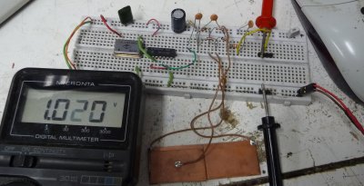
Full left deflection
Full right deflection
If it still works, you havn't messed with
it enough.
See that 1K resistor going to ground in
the schematic? it sets the zero. so now what I did was to pull it out,
and make a voltage divider out of 2.2K resistors to set it at 2.5V
instead. Why? this will keep all the output positive which is usefull
for going into an adc on a microcontroller.
With the rightfullness deflectionisity
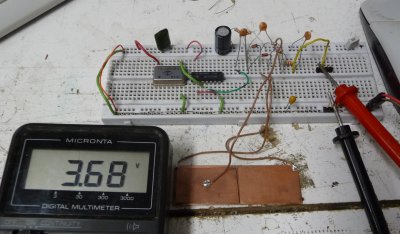
With the leftfullness deflectionisity