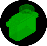
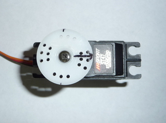
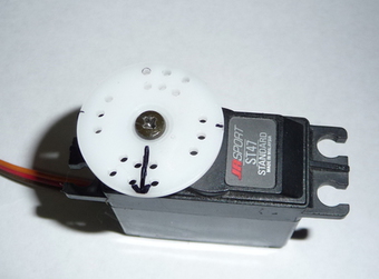
Servos have a 3 pin connector,
consisting of ground, supply voltage, and control signal. Pinouts have
been known to vary by manufacturer.
Servos are controlled by sending it a
variable width pulse (a type of Pulse Width Modulation (PWM)).
Important paramiters about the shape of the pulse are the 'centre
duration' and repetition rate. A servo often turns less than 180
degrees on the output shaft over the rated minimum and maximum output
pulse lengths.
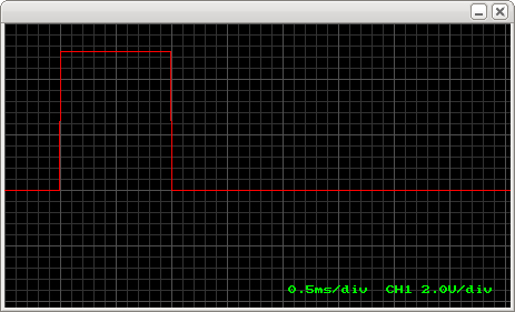
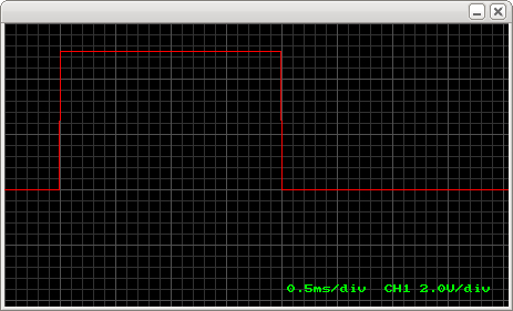
The centre position of the servo is defined by a pulse width input of
1.5ms high (it should be the shaft position in the middle of its
capable movement). The standard pulse width range is 1ms to 2ms, which
is often described as having a 180 degree difference in the output
shaft, but often does not. (you can go wider on the pulse width
changes, for example .9ms to 2.1ms which, depending on the servo, may
give you more movement.)
Every time a control pulse is sent to a non-digtital servo, it performs
a position 'correction'. The designed correction rate (pulse rate) is
50Hz, or a new pulse every 20ms, more about that later.
So, in summary, the servo expects to see a pulse every 20 milliseconds
(ms) and the length of the pulse will determine the output position.
For example:
- 1.5ms pulse will make the motor turn to the 90-degree
position.
- 1 ms pulse moves it to 0 degrees
- 2 ms pulse will turn the servo to 180 degrees
Its good to know HOW the servo controls
its position, if you know this you can pull some interesting tricks,
like adjusting the gain and force feedback.
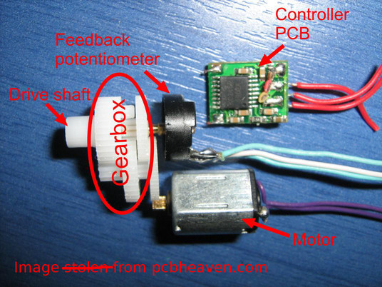
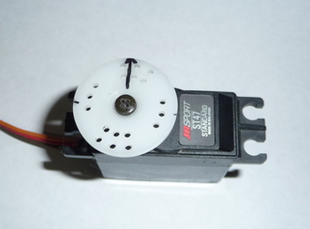
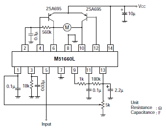
Inside a servo is a:
Motor
gearbox
potentiometer
control circuit
The motor is attached by gears to the output shaft, which is
attached to the potentiometer. As the motor rotates, the
potentiometer's resistance changes, so the control circuit can read the
output position to make any needed corrections.
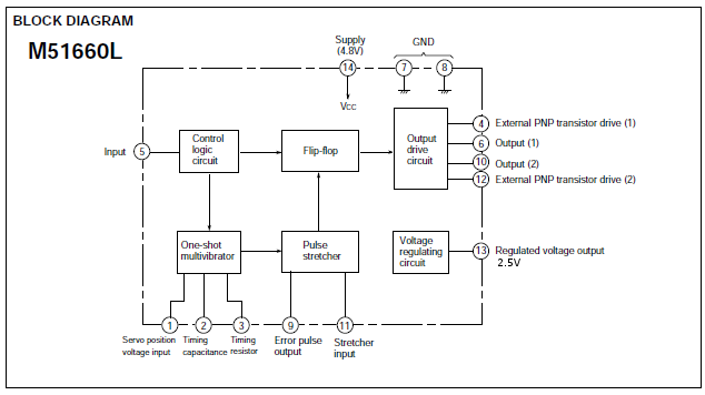
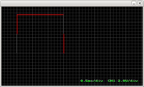
As already stated, the control signal is a pulse between 1 and 2ms long.
The internal potentiometer is attached to a circuit that also generates
a pulse between 1 and 2ms, but the length is determined by the position
of the output shaft.
This internal pulse is triggered by the start of the control pulse.
The circuits goal is to make the two pulse lengths match, this means
the servos position matches the 'joystick position'.
These two pulses are compared, to generate a 'difference pulse'.
Direction of the correction can be determined from the timing of the
difference pulse:
- If the difference pulse occurs while the control pulse is still high,
this will mean the motor has to turn, say, counterclockwise.
- If the difference pulse occurs when the control pulse is low (as in
after the control pulse finished), it would mean the motor has to turn,
say, clockwise.
The length of the difference pulse determines how much power the motor
needs to get. This gets more creative.
This is where the term 'Proportionate' (the same P as in PID) comes
from, the pulse is proportionate to the error.
What they do, is use whats called a 'pulse stretcher', this multiplies
the length of the difference ("error") pulse.
This multiplied pulse (it can be up to 17ms long. We have 20ms between
control pulses, if the control pulse is 1ms and the internal pulse is
2ms (worst case error) we have 17ms left to fix position till the next
control pulse comes along. In actuality the multiplied pulses are never
this long.) is sent directly to the motors driver circuit.
If there is no error, the motor doesn't recieve a pulse.
If there is a large error, the motor will be sent a longer pulse,
effectivly recieving more power. (PWM, the duty being the multiplied
pulse, the rate being the freq of the incomming control pulses)
It's important to note that the servo may not completely correct the
position difference within one pulse, it just makes 'progress'. This is
why its important to keep repeating the pulses to the servo.
As you can see, the motor will recieve correction power if the control
signal changes OR if the shaft position changes. This allows the servo
to hold its position like it does. Which is also why you get
'twitching' on a heavily loaded servo where the load on it can move it
back a little between pulses. (this is not related to the twitching
caused by avrlib which is a code timing issue)
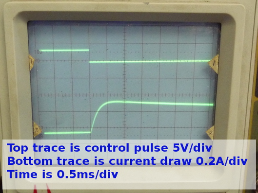
A loaded servo, will never be able to completely correct the error, so
the motor will be recieving correction pulses every time there is a
control pulse, and the motor will draw current for that period, which
is proportional to the load on it.
Did you read into this enough to learn how to adjust the average power used to correct the motors position?
Other stuff you wont find much anywhere else:
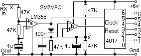
Joystick 6 channel multiplexor:
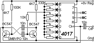
Servo 6 channel demultiplexor:
Who can tell how to expand this to 9 channels?
Who can tell how to use this to expand 1 pin of a microcontroller to operate 9 servos?
Well they thow out all the 1960's
technology in the previous paragraph and drop in a microcontroller, the
microcontroller measures the length of the incomming pulse, memorizes
it. It continiously reads the potentiometer and uses the difference in
readings to control a higher frequency pwm stream to the motor driver.
(welcome
to 1970's tech }:] ) This means that it can make corrections
without having a stream of control pulses. This allows it to get closer
to the target position between the control pulses. To my knowledge most
of these will go into 'shutdown' mode if it dosn't recieve control
pulses over a timeout period, but I'v never been able to afford the
goofy things, I usually can't afford standard servos, so I take a big
gearmotor, position detector, motor driver, and microcontroller and
make my own.