The Hardware state machine


>Hardware state machines have interested me for a long long time. For quite a while I wasn't sure why anyone bothered coming up with the CPU. I'v made a number of programs over the years to help me design hardware state machines, but never managed to get around to assembling any. As I was sitting in my shop contemplating the meaning of taking over the world, it occured to me that ANY cpu board that used an address latch could be REALLY easily turned into a hardware state machine. It might sound obscure, but a lot of baords have these, anything mcs-51 or mcs-48 based just to start with. Having just done a bunch of shop cleanout I started turning the place upside down... er no it already was.. that makes it right side up.. looking for all the boards I could find that had controllers that had required an address latch. I found 3 classes in my parts boxes, cdroms, printers, and industrial control baords.


1


> Gathering parts. I found a printer using a DIP rom package. I can program DIP eproms, so thats perfect. (I reordered the steps to how I shouls have done it) at the same time I used this excuse to make an POV led project, which was on my todo list anyhow.


2


> First thing, is to make sure that the 74x373 is what you think it is, with the pinout information for the ROM (in this case 256k) and the latch, use a multimeter to confirm that each of the data lines O0-O7 go to the latch, and come back out as A0-A7


3


> With the '373 confirmed, ditch the processor, I used a knife to cut down the sides of the chip, making sure not to cut all the traces under it, as they may yet come in handy. I also folded back any pins threatening to short out anything. The memory chips in it were masked rom so those were pulled out and thro.... filed accordingly.


4


> So the idea is to have data outputs 0-6 applied back to address lines 0-6 via the latch. This is a 256kbit rom, so we have some extra address pins to do away with, we also have a chip select and output enable that we want to lock on. almost all these pins are directly beside each other, so I'm gonna use a nice big solder brige to do it. (for any of you who have solder always bridge when you dont want it to, getting it to bridge when you do want it to is a trick and a half.) Grounded out are: A8, A9 A10, A11, A12, /CE, /OE


5


> Now as I was assembling this I realized that there would be a problem, the '373 is whats called a 'transparent latch' this means that its not edge triggered, its level triggered, and, in this application, thats a bad thing. SO, the '374 (74x374) is an edge triggered chip with the exact same pinout. Out goes the '373, in goes a '374 (in a socket, just incase)


6


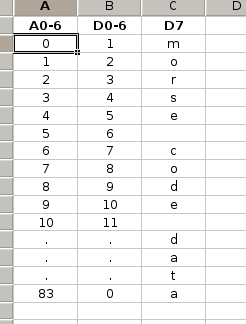
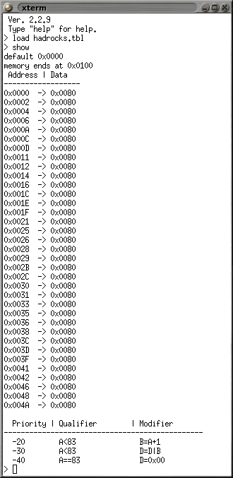
> We need software! I wrote, back in 2009, a program for generating table or equation based memory images. This allows me to take a mix of equations and defined content and build an ihex file. Designing the memory for this isn't hard, there are two parts, one is that D0-D6 need to contain the address of the next memory location, part two is that D7 needs to have the morse code data. Because the memory cells default to 0, I only need to 
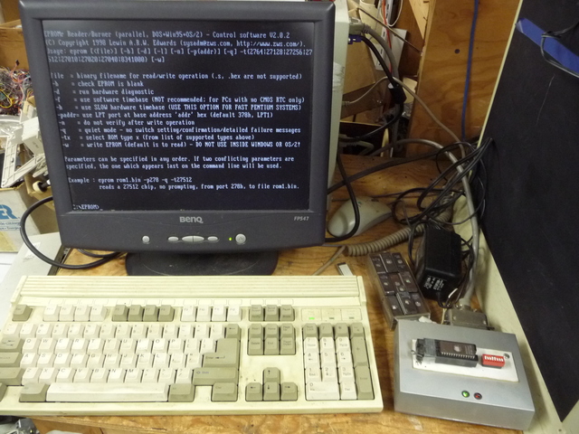
specify the 1's for the morse code. My program works via command prompt, I'm showing you the program for the memory chip without going into gorry details on how to get there. The program outputs a .ihex file, My eprom software can only take binary images, so I use ihex2bin to convert the results. oops, I wrote that too, contact me if you want a copy... My program is free to those interested, I dont have it posted, if you want a copy ask, I should clean it up just a bit before handing it out. For those interested, Modifiers are only run if Qualifier isn't 0, A is the current address, D is the data for that memory location rules are applied against each memory address from highest to lowest, positive rules before literals and negitive rules after literals.


7


> The project needs a new memory! Time to unburry the eprom station! used one of my nice new high-density floppies to transfer the file to the eprom burning station, YAY TECHNOLOGY!


8


> In goes the memory chip! Also appling power to the baord (from a bit of a distance, lotsa parts torn off that and I wasn't quite sure if there were any shorts, but its a supply with some current behind it, so it should be able to clear any minor shorts) and I used one of my freq genorators to inject a clock signal to the /LE (clock) of the 374. Every time this latches it caused the new current address to be transfered from the data bus to the address bus. Also stuck the 'scope to the morse code output pin. Note the resistor, because I'm not using A7, I need to ground it. I actually hacked this hack by forcing D7 to miss the socket so I could tap off it. AND YAY! IT LIVES! (first time too)


9


> Independence! it needs its own clock source. The only source of clocking on the board seems to have been cut off with a large knife, so, I found a really ugly 74C14 and piggybacked it to a 74ls04, next I used a spare SMT resistor off a motherboard and some decoupling caps to make an oscillator. Its my fav kind, you put a resistor between in and out of a gate, and put a cap between the input and ground. Quick test to see if it oscillates and all is good! The latch line from the '373 had gone to the processor, bit of work with the meter to find where and some jumpers to connect it in.


10


> LIGHTS! Next the project needs to drive an led. This is an impact printer baord, so there just happen to be lots of drivers on it, some that I havn't even torn off yet! so I selected a channel and attached the led. The only voltage on this thing will be 5V, so I jumped the nearest power line and the 5V togethor.


11


> Power! ok, I was GOING to use a stepper as a genorator that would be plugged into one of the origional stepper ports, and the flyback diodes already in the circuit would feed the power to the origional motor driver rail, which I would regulate down and use for a 5V supply.... but life is short and I'm not getting any younger. so, I grabbed a battery, and a 7805 and did it the easy way.


12


> ok, sorry no pics of this... I taped the works to a broom and spun it around while my roomate tried to figure out how to operate the camera these things are trickier than they sound! After about half an hour of new batteries, field adjustments, and minor bruses, we got a half descent image. The dashes are twice the length of the dots, hindsight, longer next time!, I'v dimmed the extra field to make it easier to pick out the morse, read it clockwise.


13


> You think that took a long time? it did, but I think writing this article about it took longer!


-


> Field adjustments. seems that origional .1uF I used ran too fast, so I upped that to .47uF, also, dispite all my care, the morse line was inverted, fine thing to find out after 15mins of trying to get a good pic. so I commadeered a gate off one of the 74ls04 chips on the board.

Help Rue build a 12' mecha, donate spare washing machine valves, donators get their name on it!