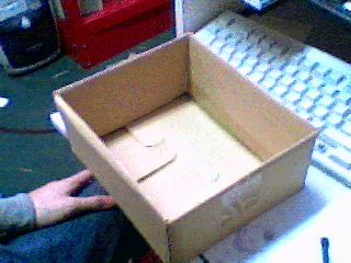
Figure 1.1. An all-mighty box.
The single most important part of your project is the box. The box will hold all the parts and documents of the project, wether you have decided to use them or not, wether the project is active or has been on the 'back burner' for 4 years. Embrace the box, do not under estimate its power. Figure 1 shows the box I have carefully chosen for this project. Choose your box based on your project, your box should be no smaller than 80% of the size of your project.
Figure 1.1. An all-mighty box.
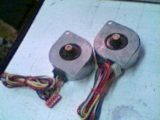
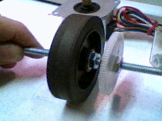
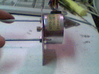
I'm going to make step 2 the search for motors. For this robot we need a matching pair of motors. I have decided to go with stepper motors, and chosen the two depicted in figure 2.1. These are from inkjet printers. I recomend wrapping the motors wires up, it will keep them from getting in the way and broken.
Figure 2.1 Two matching motors.
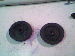
Wheels are the next most important thing I go searching for. What I find are paper feed wheels from another inkjet printer. They are shown in figure 3.1.
Figure 3.1 Wheels.
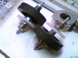
Ok, now that we have wheels and motors, we need to hook them up to each other. Few motors on the world are strong enough to directly drive wheels, and these motors are no acception. The key to solving this problem is to give the motors a mechanical advantage. In applications terms, this means adding a gearbox. It can often be exceedingly difficult to find a gearbox that works well for such a project and is able to bear the weight of your robot. If you find such a thing you are lucky. If you find a matching pair of them you are even more lucky. If you bought a matching pair, you are a copout. I will be building the gearboxes for this robot. I have developed a 'sandwich' style, that works ok. Alignment of gearboxes is critical, so get it right.
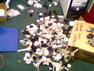
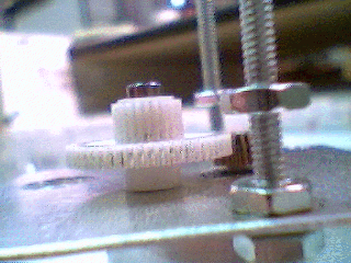
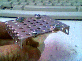
The first stepof building your gearbox is to find matching gears, you can see in figure 4.1, I have started sorting matching gears from the collection.
Figure 4.1 sorting a collection of gears.
The next step is to isolate the gears that mesh properly with the gears on the motors. Of those, select the largest gear possable, that is somewhat smaller than the wheel. This gear will be attached to a shaft with the wheel. It needs to be as big as possable to give you the most power you can get, but must be smaller than the wheel so it dosn't "drag" on the floor. Figure 4.2 shows a gear I have selected for this.Step 5)
Figure 4.2 The main drivegear selection.
One final problem remains. The gear, although it be big, is not large enough to cause the motor to clear the wheels axle. To solve this, I add another reduction gear. This will be shown in later steps.
With the main parts selected, we may now begin some assembly. The first thing to do is to assemble the axles. The axles must:Step 6)
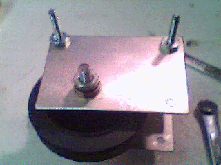
To make it easy to attach everything to the shaft, I will use prethreaded rod for it. This makes it easy to attach the wheels and gears, but creates a problem with holding the weight of the robot. Just putting the threaded rod through a hole in sheet metal will cause it to get worn away really fast, for this reason I will use bushings over the rod. The holes in both the wheels and the gears I have seleced are too large. To solve this problem I find a combination of rod size, and some pipes to ack as shims. The wheel and main drive gears are attached to the axle, as shown in figure 5.1. This solves the first two problems on our list. Both the wheel and gear are "sandwitched" between nuts on the threaded rod. This is merly a prefit, the exact spacing will be worked out as the project goes togethor.
- Hold the wheel
- Hold the main drive gear
- Turn
- Carry the weight of the robot
Figure 5.1 Wheel and gear attached to shaft
The next thing to be done, is to add the bearings for holding the weight of the robot. After digging around I find a set of bushings that do the job. What we end up with is shown if figure 5.2. It consists of #10 rod, #10 washers, some pipe and cintered brass bushings.
Figure 5.2 completed axles.
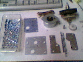
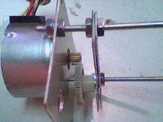
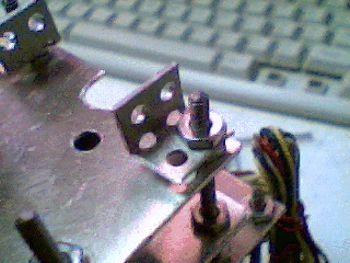
The next step is to ready the gearboxes for assembly. I won't go into designing these pices, I'll save that for later, less it be said, the process is a lot like assembling it. Figure 6.1 shows all the pices of a gearbox ready to be assembled. The parts are as follows, top left: 6-32 nuts, going right, axle support plate, motor, axle, below axle is the intermediate gear, and left of it, its pin. Bottom row, is the motor plate, holder for intermediate gear, 3 pices of 6-32 threaded rods, and the retainer for the intermediate gear.
Figure 6.1 Gearbox pieces ready to be assembled.
When trying to make a robot in 10,000 steps, be sure to break almost everything up into a step. I realize I have passsed up a lot of opportunities to do this, this time. I promise to make it up in the future.
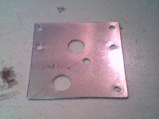
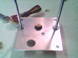
So, the assembly of the gearbox starts with the motor plate and the motor. Figure 7.1 shows the motor plate. This plate holds the motor, the intermediate gear, and one side of the axle. The top two holes in figure 7.1 are for mounting the gearbox later.
Figure 7.1 The motor plate.
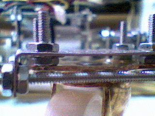
The first step of assembly is to attach the motor. As seen in figure 7.2, the motor is bolted to the plate with the threaded rod. Nuts on either side of them hold it all togethor. Normally, the threaded rod would be left longer on the motor side, but on this device, the motor it too close to the threaded rod and does not allow nuts to be turned. The rod could be left long enough to extend past the motor, it wasn't deemed that crutial.
Figure 7.2 Motor bolted to motor plate.
With the motor on its back, the assembly is ready for more layers of parts, as shown in figure 7.3.
Figure 7.3 Motor bolted to plate, ready for layers of parts
The next fews actions underline the general theme of the robots construction.Step 9)
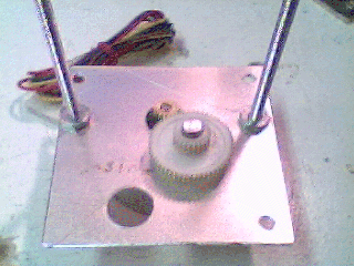
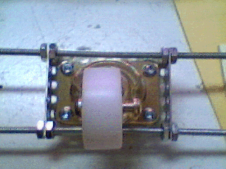
The next layer will hold the intermediate gear, so the size of the gear determines the height of the layer. Therefore we place the intermediate gear, and its pin. This is shown in figure 8.1. As you can see, the pin fits into a hole in the motor plate, but it blocked by the motor itself. To keep the gear in the desied position, a prefit found that a washer should be added, as shown in figure 8.2
Figure 8.1 Placement of intermediate gear.
Figure 8.2 Spacer washer and standoff nuts.
Figure 8.3 Positioning of nuts
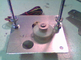
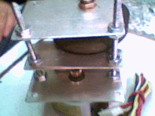
Nuts are put on the threaded rods, these are deemed "standoff" nuts, they will determine the spacing of the next layer of parts.This is shown if figure 8.2 and 8.3. From 8.3 you can see that the nuts are places so that the top of them approximitly lines up with the top of the gear (not its pin, the gear itself)
The next pices to go on will hold the intermediate gear in place. Figure 9.1 shows the first plate of the two plates that hold this gear. Note how the top of the plate is flat with the top of the gears pin. If this plate were left like this, the pin would be able to slip out. Figure 9.2 and 9.3 show the next plate. It holds the pin from falling out.
Figure 9.1 Intermediate gear plate.
Figure 9.2 Top view of pin retainer plate.
Figure 9.3 Side view of plates for intermediate gear.
The next step are addition of the lockdown nuts. You can see these in figure 9.4. These nuts hold the two plates against the standoff nuts. Now the intermediate gear is locked in place, it cannot move from side to side because of the retainer plate and the motor, the holes in the two plates hold it in place. There is no 'squishing' force on the gear, so it can turn freely. The positioning of the two plates can be adjusted by moving the standoff and lockdown nuts a little.
Figure 9.4 Lockdown nuts added and spacing adjusted.
WHERE 1/1000'TH OF THE WAY THERE!Step 11)
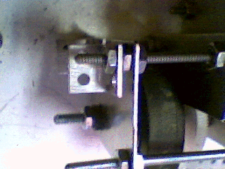
Now we do the same thing that we just did with the intermediate gear, but with the axle. Figure 10.1 shows the axle put in place. Figure 10.2 shows how the axle aligns with the intermediate gear. The axle had its spacing adjusted a little with washers.
Figure 10.1 Top view of axle put in place.
Figure 10.2 Side view of axle put in place.
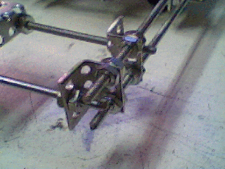
Now we add standoff nuts, seen in figure 10.3, they are positioned to align with the shoulder of the axles bushing. After that we add the axle support plate, space it and add the lockdown nuts. The results is figure 10.4. We dont need retainer plates for the axle because the axle is locked in place by the shoulders on the bushings. Note that the bushings shoulder on washers that shoulder on nuts that are tightened down on the threaded rod. The axle is not 'clamped' in, that would cause excesive friction.
Figure 10.3 Standoff nuts.
Figure 10.4 Axle plate locked down.
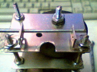
You can see the 'sandwich' that has developed from this method in figure 10.5.
Figure 10.5 Sandwich of parts.
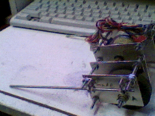
The next step is to insert a final pice of threaded rod to sturdy up the layers. the rod is places in one end, as in figure 11.1, two nuts are added, one side is locked down, the other nut is positioned, and a lock nut is added. During this process the nuts can be used to jack apart or clamp the two plates in order to correct their spacing. In this gearbox, the two sides needed to be jacked apart a little, this is shown in figure 11.2.
Figure 11.1 Rod inserted, and nuts added to inside.
Figure 11.2 Plates jacked apart slightly, last nut not yet locked.
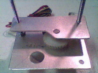
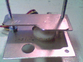
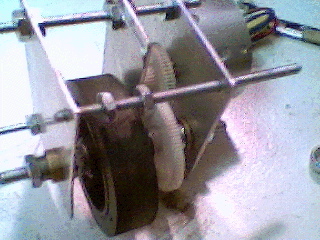
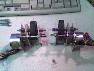
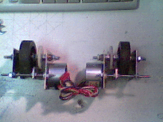
This process is repeated to create a matching gearbox for the other side. Care is taken to assemble it in "mirror" to create a left and right set of gearboxes. These are seen in figures 11.3 and 11.4, where the decision is also made to use the set in the 'wide' configuration (11.4)
Figure 11.3 Gearboxes in narrow config.
Figure 11.4 Gearboxes in wide config.
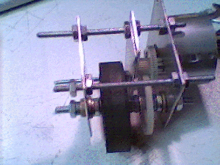
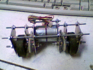
The next step is to bolt the two gear boxes togethor. I have done this in two places, in figure 12.1 you can see that I have taken out the two bars that were put in in figure 11.1 and 11.2 and replaced them with one bar that goes all the way across.
Figure 12.1 New cross bar.
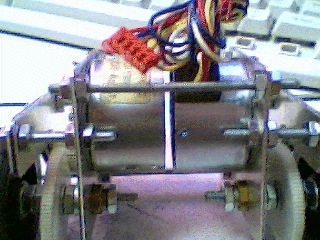
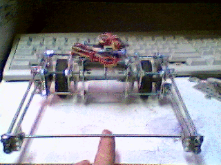
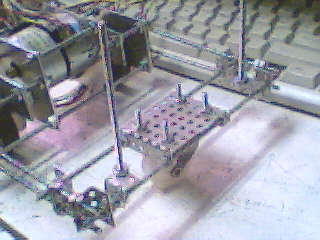
When building anything structured like this, you want to make sure you have atleast 3 points holding it all togethor, so, as you can see in figure 12.2 I have used the holes that were put inteh top to tie them togethor too. Now that the two gearboxes are attached to each other, the frame can be finished off.. The gear boxes were the hard part.
Figure 12.2 New bars holding the tops.
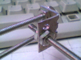
So. To build the rest of the frame, we need some tiepoints, these are created using some of what I call cut-n-nut. As you can see in figure 13.1, there is a "2x3" pice of cut-n-nut bent and bolted on to the extra length of the top lugs on the frame. These allow us to use the threaded rod to run lengthways down the frame, as shown in figure 13.3.
Figure 13.1 First of the frame brackets to the gearbox.
Figure 13.2 Front view of bracket placement
Figure 13.3 Runner placement.
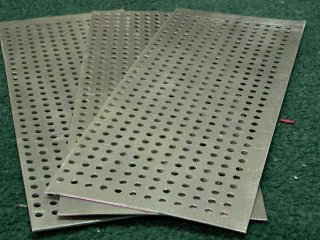
In figure 13.4 you can see two of the runners attached, they have just been fastened with nuts the same way everything else is assembled. To sturdy the frame up, a second runner is taken off the bottom post of the gearboxes also (the long one that goes all the way through). Figure 13.5 shows that, with a cross piece being test-fit. If your interested, figure 13.6 shows a closeup of that joint. Figure 13.7 shows some raw cut-n-nut, the pieces used on this robot are cut and bent from this. I'm using 18 guage aluminum cut-n-nut, with 9/64" holes spaced 9/32".
Figure 13.4 Two of the runners attached
Figure 13.5 Two runners on each side.
Figure 13.6 Closeup of test junction.
Figure 13.7 Three nice, new pices of cut-n-nut.
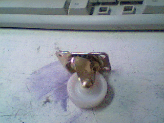
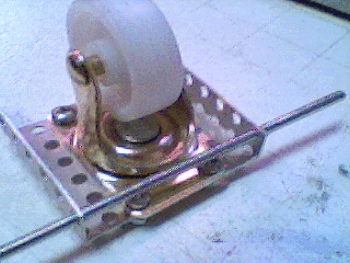
These drives and frame are great, but they alone won't hold up a robot. Therefore we are going to add a caster to support the robots butt. After a while of pacing up and down the isles at the hardware store, I found the ideal solution, as seen in figure 14.1. This wheel will allow the robot to roll, and will play along if the robot wants to turn.
I bet your wondering "but what about the BOX!, you said it was so important, and you havn't used it yet!" Ah, thats where your wrong, at this verry moment the box is holding the gearboxes, the casters, and a bunch of other parts that are still a secret.
Figure 14.1 Mini Caster wheel
To attach the caster wheel to out robot, were going to use more cut-n-nut Figure 14.2 and 14.3 show the basic idea, the supporting threaded rod can fit through the folded tabs in the cut-n-nut without interfearing with the casters movement.
Figure 14.2 basic caster attachment.
Figure 14.3 Threaded rod through cut-n-nut.
So with that said, two rods can be attached to the cut-n-nut holder. It is also a good idea, if the threaded rod dosn't cover the access to the screws for the caster, this can be done by turning the caster 90 degrees to how its shown on the next few photos. Figure 14.4 shows both rods bolted on. Figure 14.5 shows a closeup of the placement of the nuts to bolt it on.
Figure 14.4 Two bars bolted to caster wheel clamp.
Figure 14.5 closeup of rod attachment.
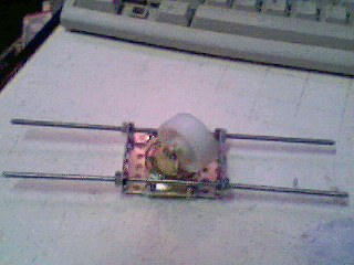
Now there are two pieces of frame to be attached to each other, they will be attached much like the single bar in figure 13.5. Figure 15.1 shows a closeup of how this is done with cut-n-nut. The fact that everything is on threaded rod means that by turning the nuts, you can do really find position tuning. The caster wheel is placed in the centre of the back of the robot, as seen in figure 15.2.
Figure 15.1 Closeup of caster and frame attachment.
Figure 15.2 Overview of wheel placement.
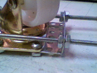
It was mentioned that the wheel should be mounted 90 degrees from where its shown, at this step another reason comes to light to do that. In figure 15.2 the butt of the robot is a little low. By simply re-arranging the parts we have used, this can be made adjustable. This is shown in figure 15.3 and 15.4, the mounting nuts are used as spacers, because the remaining gap is smaller than a nut, washers are used to space it off.
Figure 15.3 adjustment for caster height. Side view.
Figure 15.4 Rotation of caster to allow height adjustment.
That concludes the major mecahanical work. Next we will start with the electrical systems.
We will need something to fasten down electronics, I have opted for this chunk of plastic that I cut out of one of the paper sorting things that I don't need because I don't sort paper, I heap it, just like paper should be.Step 17)
Figure 16.1 A random chunk of plastic cut off something. its about 1/8" thick
Then we need a way to bolt it to the robot. I have chosen to hold up one end with threaded spacer (its cut-n-nut, really it is) These have been made longer than they will probably be needed, this is because its extremly likley that they will get used for more as the robot goes up. Changing these things later is a pain, as you will already know if your building one now.
Figure 16.2 Posts for holding up one side of circuit mounting plate.
For the back of the robot, I'll just use cut-n-nut, this is because the back of the robot is much higher and does not need to be adjustable.
Figure 16.3 Brackets for holding back of circuit mounting plate.
Next we punch our holes in the chunk of plastic and bolt it on. the correct hole size for the #6 screws is 9/64. Thats not what I use, I go one size up (5/32). This allows the allows reality to correct for my design. I start by drilling the front set of holes. Fitting it on, and then marking and drilling the back holes. This, again, accounts for correction of reality. I also take the opportunity to drill holes for the motor wires.
Figure 16.4 Drilled, mounted circuit board mounting plate.
Any good electrical system need one essential thing, electricity. This will eventually take the form of batteries, but not right now, I'm going to have this bot online 24/7 for a while, and batteries just wont do. What I will do is hook this up to a power supply via a teather, and because thats easy I'll put it off till later.
The next thing this robot will need is a brain, all good robots have brains, some robots share brains..
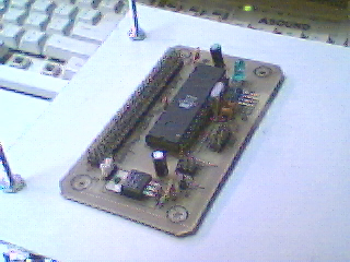
The brain I sill be using for this robot is a babyboard III, it uses an atmega32 processor, has the ability to control 31 devices out of the box, and best of all I have a few on hand.
Figure 17.1 Babyboard III, the brain for our robot.
Now that we have a brian, we can start to lay out the things that it will operate, and the other systems we will need. I have come up with the following list:
Again, it will need a power supply, but we will not have a hard time disgnosing that if we forget to put one in later.
- Serial link to computer for control
- 2 motor drivers for the two motors
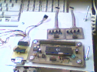
With that, I gather the required modules. Locations are worked out for the components, the controller is bolted down.
Figure 17.2 controller mounted and layout of remaining modules.
Next we drill the base plate more and mount more of the modules. Here are the motor drivers mounted, I used legths of cut-n-nut to sandwitch it.
Figure 17.3 Mounting of motor drivers.
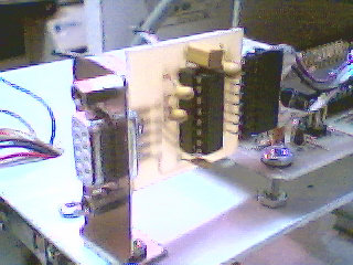
Here is the RS232 buffer mounted, a modified piece of computer backplate makes for a nice bracket.
Figure 17.4 Mounting of serial buffer.
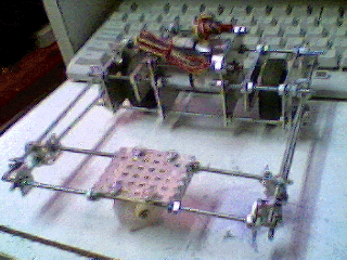
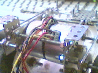
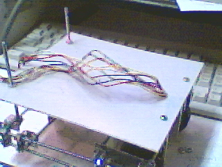
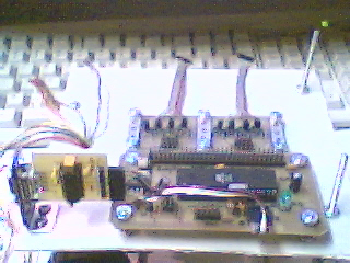
Ok, so in overview, we now have everything there, we will use a teather for power for now, as we will use a serial cable for comms.
Figure 17.5 All the stuff is there, we just have to patch it togethor and add code.
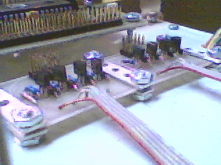
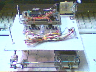
And here it is wired, it still needs a power supply, but thats easy.
Figure 17.6 This robots' wired.