Absolute position scanner (and heading too)
Do read all the way through this one to get an idea of whats comming up
as there are alot more skipped steps here than I usually have.
This is the laser scanning head for a positional system for robots
where by the robot lies within 3 beacons. the robot scans a laser
around it and when it hits the beacons they 'call their name' and
the robot measures the angles between them. It can use the known
location of the beacons and the known angles to find its position. I
will be/have posted the other parts of this system. my implementation
is going to use an avr as the robot controller and the scanner.
You need a pen laser, pipe thingy for a lamp, stepper motor, gear, small mirror... dont forget a box.
First thing we need is a stepper motor
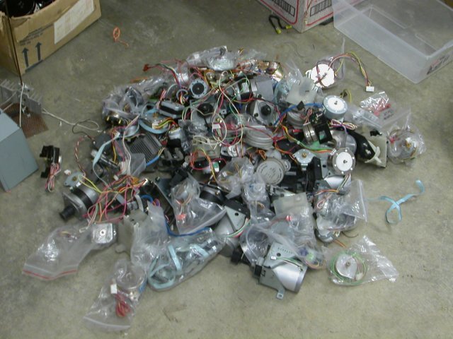
find wossy stepper motors preferably with gears on their shaft
Next we need a gear
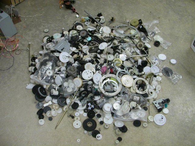
select the largest gears you can find that match up with the gears on your steppers, here is what I found
I found two sets that matched up
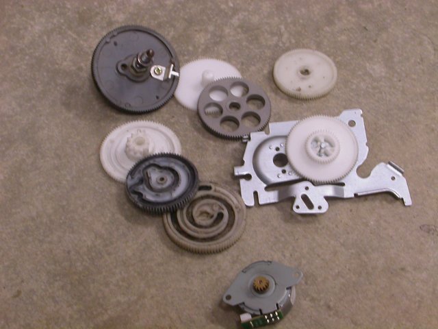
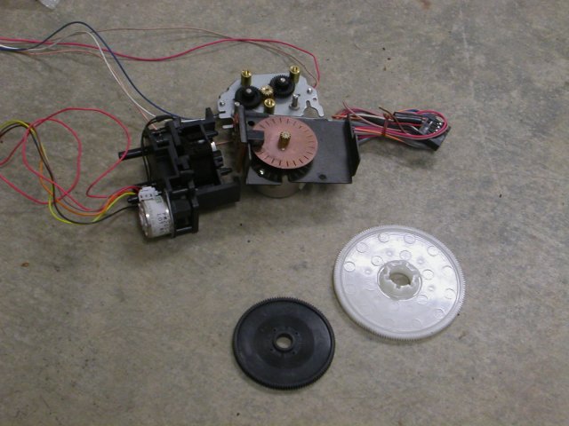
Of those choose the option with the largest reduction ratio
comparing my two best...
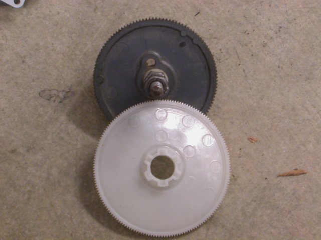
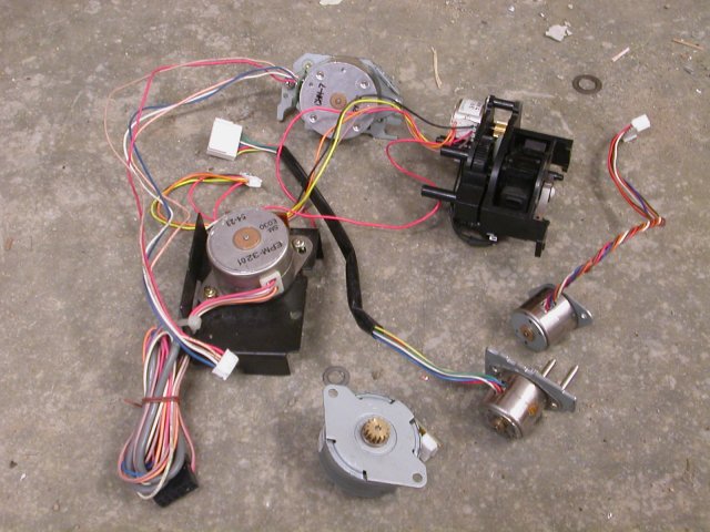
the white one wins, this brings it down to a selection of 1 of 3 mtors
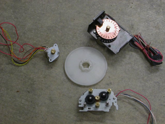
The one on the left being the smallest, woosyest motor, the one on the
right beign the smallest pinion gear and sporting an encoder wheel, and
the one at the bottom having absolutely nothing going for it at all.
A quick test of the motors to get an idea of their operating voltage
shows that the lower motor (that had nothing going for it) is 6.4 Ohms
on the coil, as the current in these is usually not higher than .25
amps, it indicates this motor takes something other than the 5 or 12V I
want for this system. goes back in the box.
The tiny motor has a resistance of 78 Ohms, the one with the encoder is
52 Ohms. This indicates that the one with the encoder may be a better
choice if running this all on 5V. It also tells us the one with the
encoder has more torque, as the current at a given voltage will
be higher = more power.
I still want to know the resolution of them both, so I'll slip togethor
a little piece of software to rotate a motor 200 steps. For a 1.8
degree stepper this would be 1 turn, for a 7.5 this will be a little
more than 4.
Surprise! none of them meet the resolution requirement! The tiny one is
18 degrees/step, the one with the encoder is 15 degrees/step and the
remaining one is also 15 degrees/step. This could be workable if I
added more gears, but I dont want to, and I want the resolution I get
from a 1.8 degree/step stepper motor, part of hte goal is to get better
than 1 degree resolution on the scan. I would also like to do 1 rev in
~ 1 or 2 seconds so that the error from the robot not stopping would be
negliable.
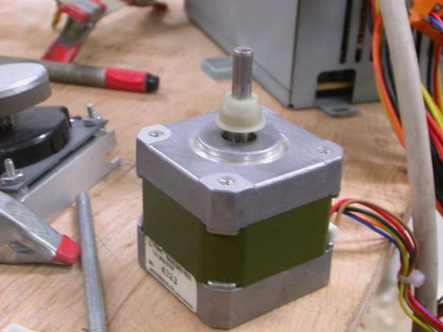
BACK TO THE MOTORS!
Turns out there are fewer 1.8 degree motors than I thought, and their not as small as I was hoping.
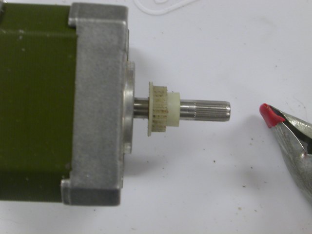
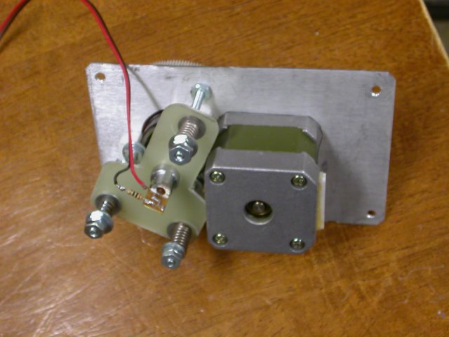
Here is the winning motor, I had to find a small matching gear to the
white main one I am using, drill it out and press it on, I'll skip
those steps cause their all straightforward.
Next we need a bit of lamp pipe, were gonna need a pen laser too, each of these is about $1
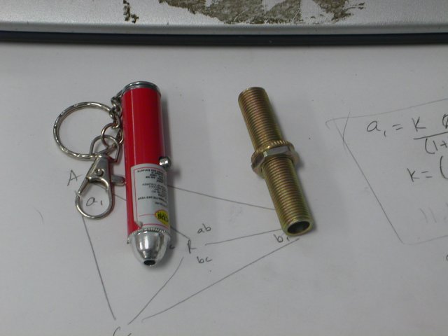
This threaded pipe will be our shaft. They come in kits for lamps with a few nuts, were gonna need 4 nuts.
We need a bearing big enough to go around it. To the bearings!
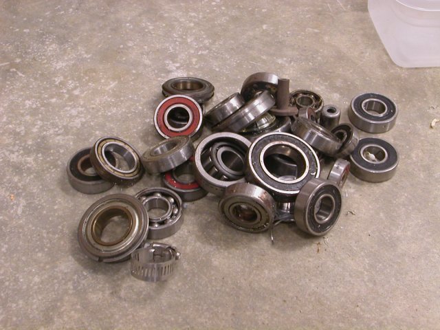
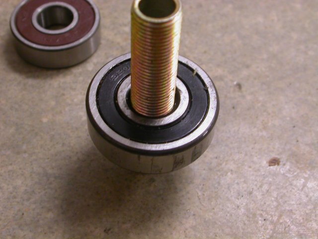
This one fits quite well...
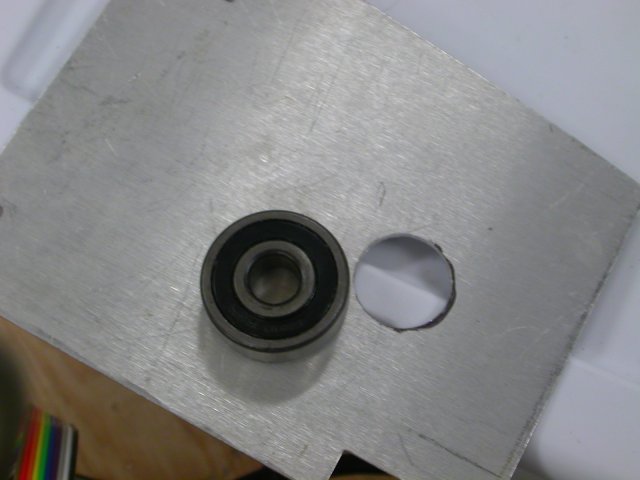
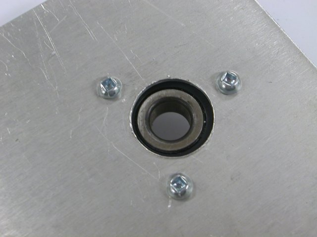
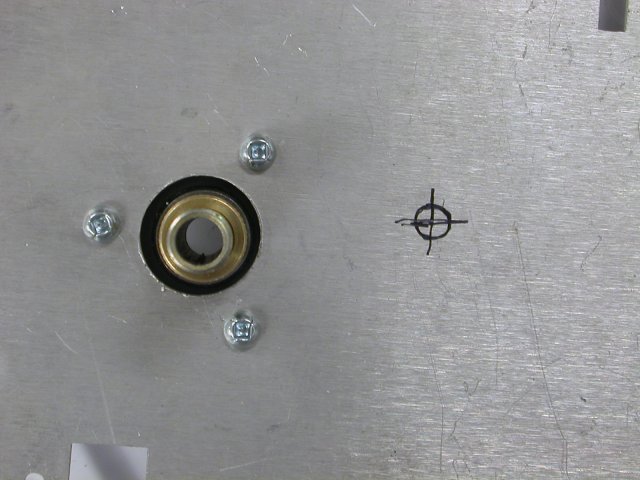
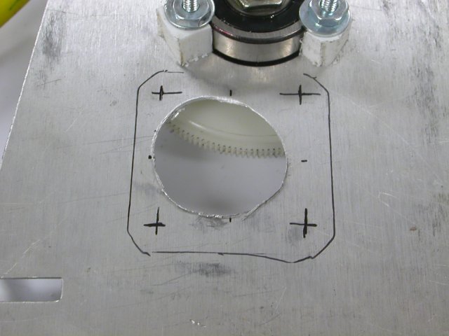
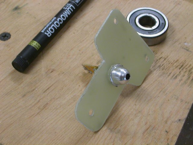
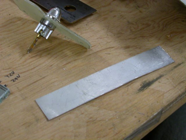
This bearing entire device can be build around a sheet of aluminum,
find one thats going to be big enough, and drill a hole smaller than
the bearings outter size. It needs to be big enough to clear the nuts
that came with the lamp pipe bits.
Next, drill 3 holes around the bearing, use 9/64" or so bit for the #6-32, the 3 screws will hold hte bearing in place.
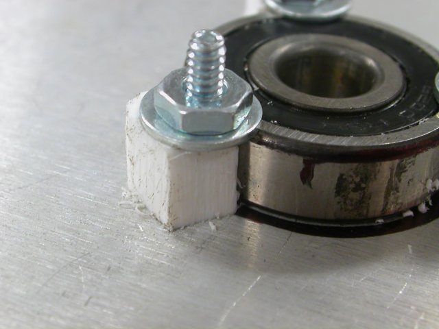
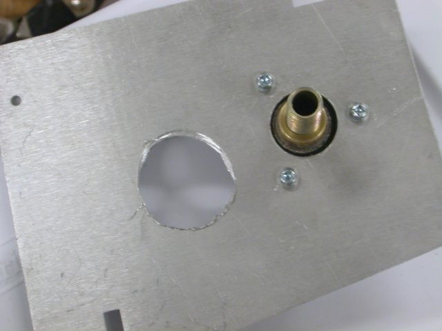
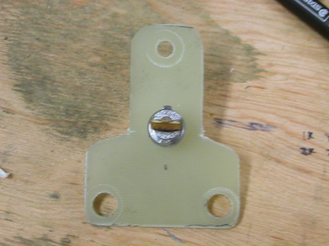
On the other side I used some plastic to shape some support blocks, I
just did it up with a file, you can use little bits of pipe, the idea
being to support the washer on teh far side from the bearing. You can
also make another piece of sheet metal with 3 matching holes and
sandwich the bearing in there.
ok, now, my gear is a little loose for this piece of pipe, if you have
a gear thats a little small you can just drill it out, but this one I'm
going to have to make a collar for.
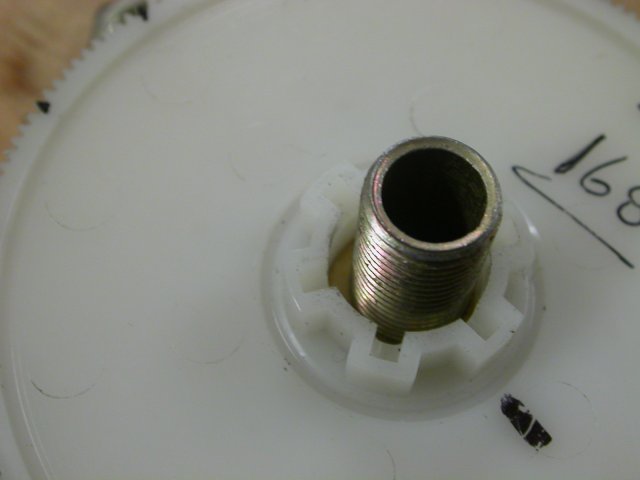
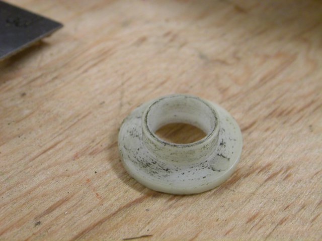
I managed to find a plastic ring with the right size outside to fit the
gear, and drilled out the inside to fit the lamp pipe. Plastic
pipe is how I usually like to do this, otherwise, a coil of thin sheet
metal also works.
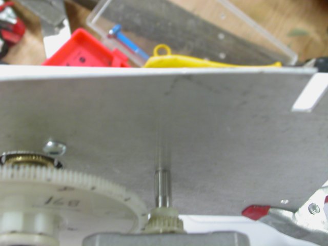
Preassemble the gear onto the lamp pipe, through the bearing, and we
will mark where the motor will be when its meshed up against it.
This motor has a collar on it (part of it) so the motors hole has to be
a little bigger than that so it will fit through and we will still have
some room to move the motor to adjust the gear spacing
so drill (or in this case maul) your hole with that middle
Be sure to file the burrs off.
now re-fit your motor, with gears meshed properly again, and work out
the mounting hole locations. I did this by tracing out the motor, then
measuring the spacing of its mounting holes and drawing them out
I'm going to do this adjustable rather than accurate, so I need to
overdrill the mounting holes too, this will give me a little room to
move the motor around and adjust the gear mesh. Drill the holes and
with the gears on, bolt the motor in place. I could only tighen two on
my first pass, then I took the gear off to do the other two
Set that lot aside and we will build the mount for hte laser.
first we need to adjust our pen laser a little by removing the case. These are pressed togethor so I'm gonna cut the case off.
with the corner of a file, cut the tube so you can split it
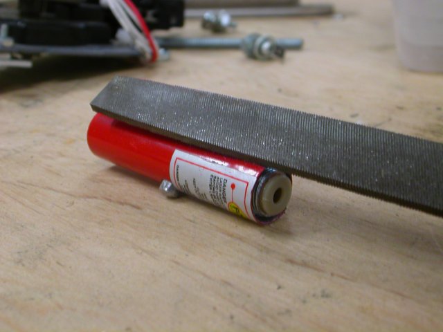
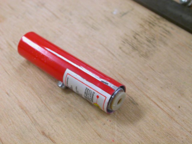
with that cut, peel back the corners and the laser assembly shoudl fall right out
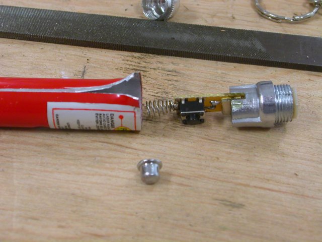
tear off... I mean, remove the spring and button, we wont be needing them
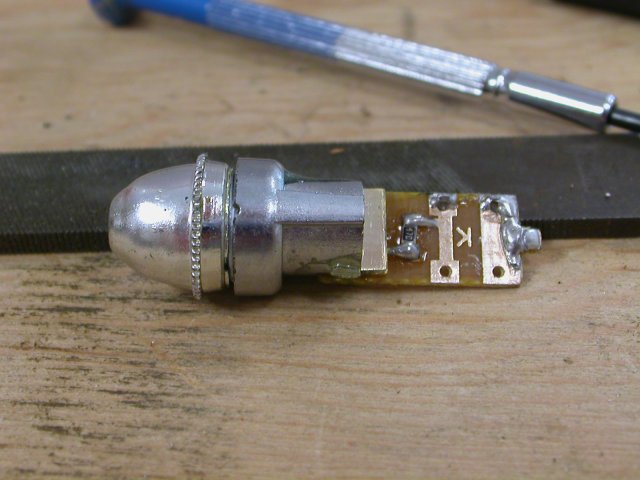
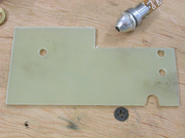
Next we need some non-conductive, but not too thick material for
mounting the laser on. I was able to find a scrap of blank circuit
board thats just perfect.
we want to build a triangle so that the angle of the laser could be adjusted. The laser needs to sit somewhere in the middle.
Cut file, and drill.
its held on by the tip piece being used as a nut
I'v overdrilled the holes in my board so I can do more of that alignment stuff
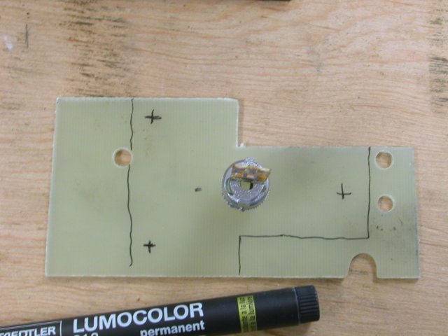
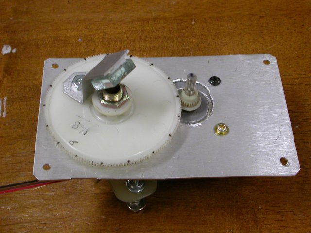
we will be mounting this behind the pipe thusly, with a small piece of mirror on the gear to direct the laser beam
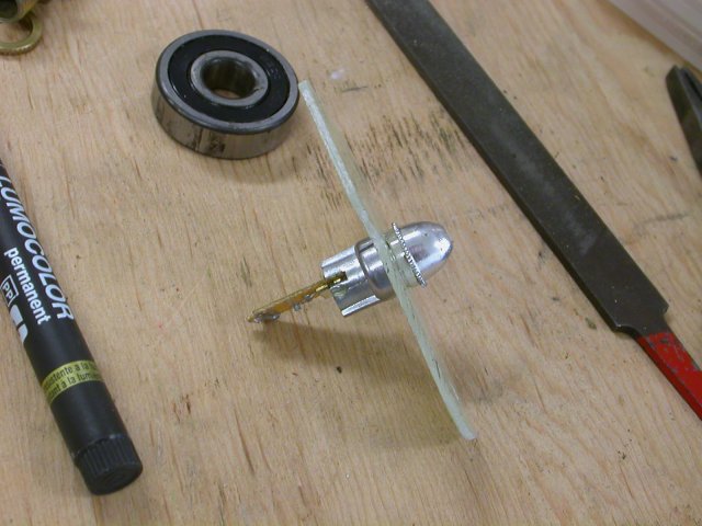
so next lets make that mirror:
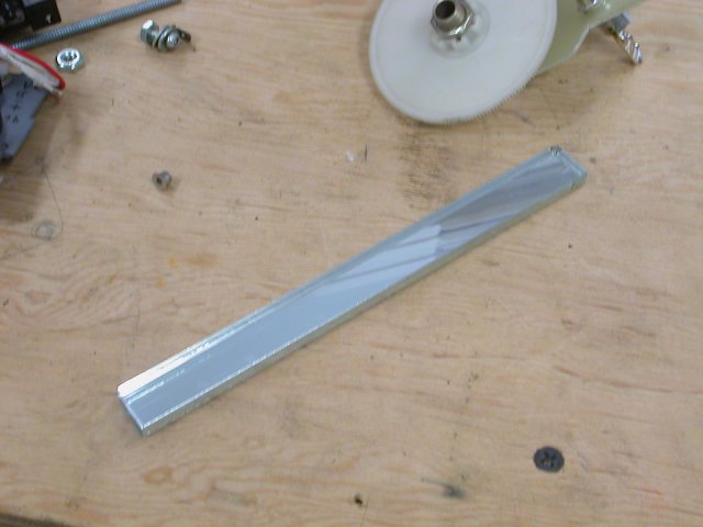
I managed to find a stick of photocopier mirror, which is sufficient:
you can cut glass by scoring and snapping it, it can be really trickey to get right, wear gloves so you dont get cut.
This piece I can file a groove into
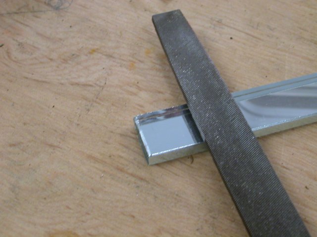
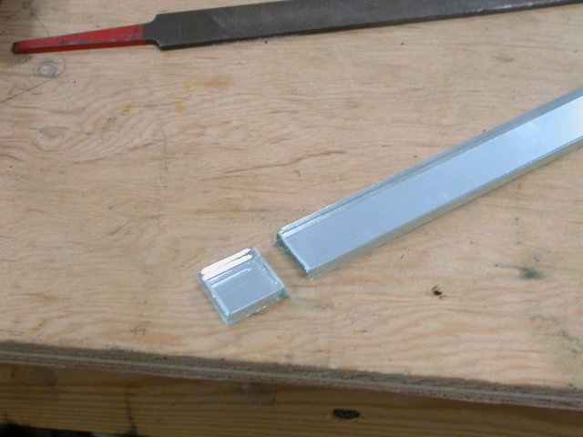
once you have scored a groove you can put some pressure on it to snap
it, you should put the pressure on it such to bend it away from
the score. The deeper the score, the better this works.
Next we will make a bracket to hold the little piece of mirror at 45 degrees above the lamp pipe
For this I'm using a strip of aluminum.
bend the end at 45 long enough to atach to mirror to, and 90 at the other end to mount to the big gear.
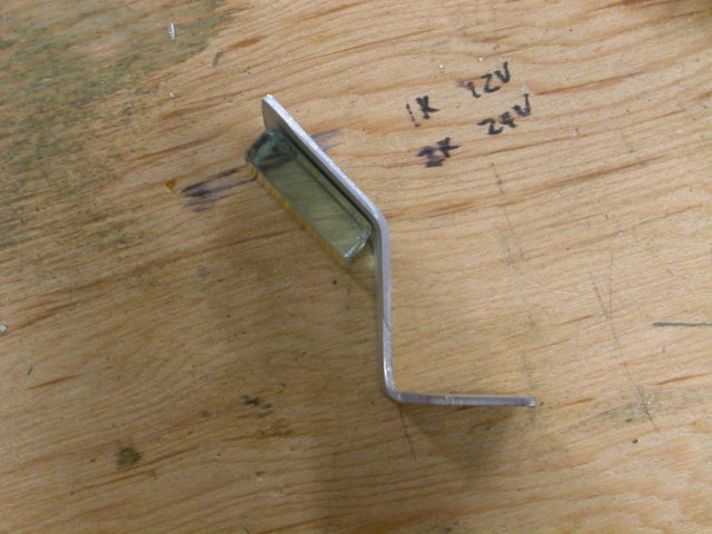
drill a hole in the part that goes to the gear for bolting it on
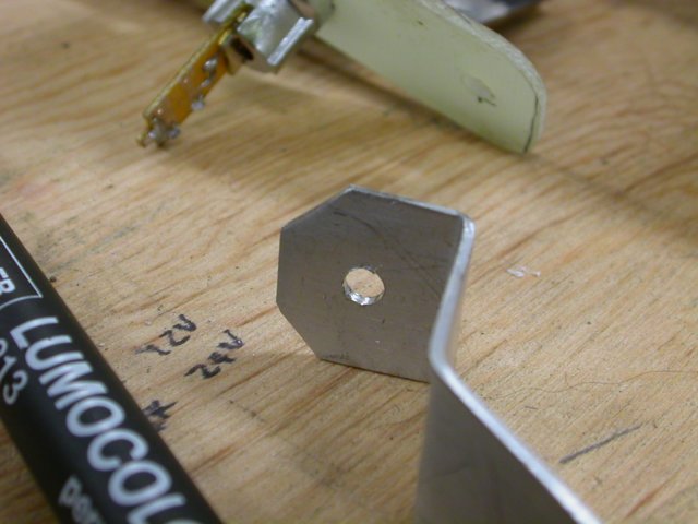
By drilling a hole through the gear, you can bolt it on, I'v used double sided sticky tape to mount the mirror with.
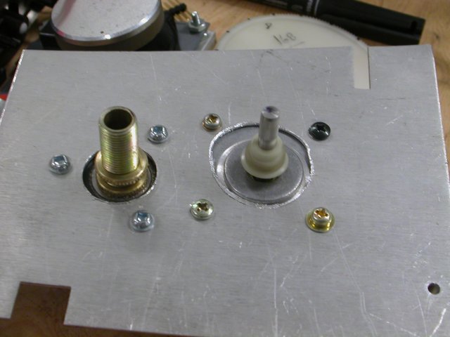
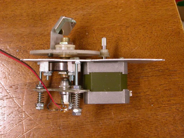
I should note that the final assembly order along the threaded pipe is
nut bearing nut space nut gear nut
this way, you can adjust the distance of the gear from the 'frame'
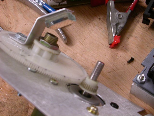
Make sure the beam can clear your motor shaft.
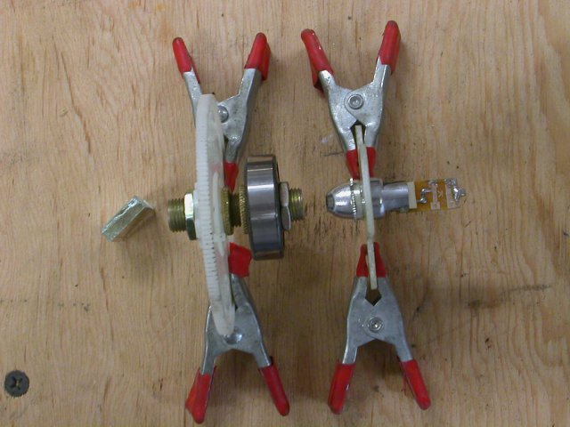
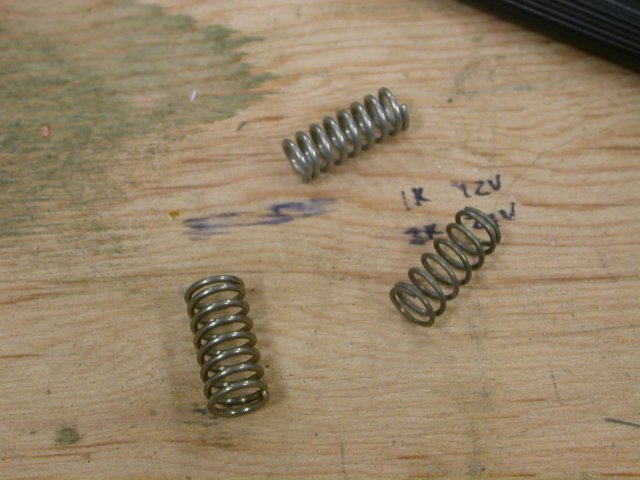
For the laser mounting we want to find some springs to do a nice little adjustable setup here
To the springs!
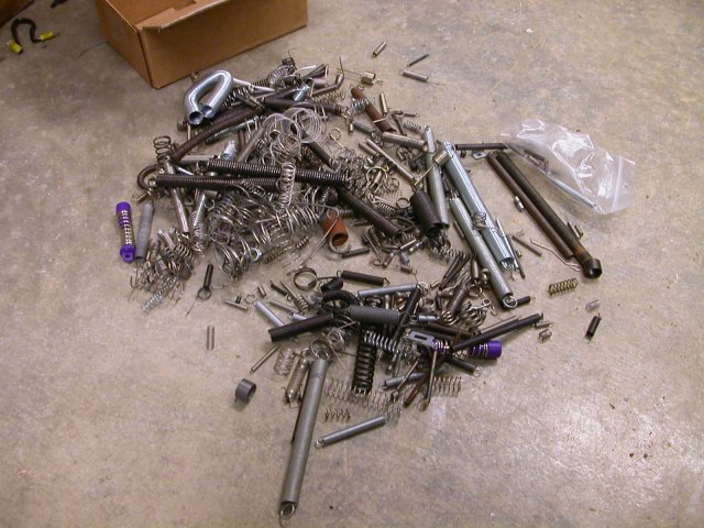
We want to find 3 that are about the same, compression springs...
This will be held on by some long bolts, which also allow us to adjust
the lasers position. Align up the laser with the threaded pipe, mark
and drill your mounting holes, I used 9/64 for the #6-32 bolts I'm
using.
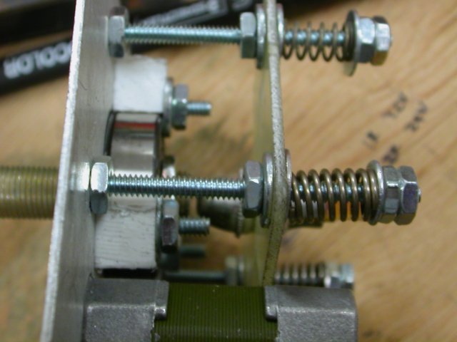
key points:
- the head of the bolt is on the left, the first nut keeps it secure to the main plate.
- the next nut is an adjustment nut, you may want to double this so you can lock them togethor when its adjusted right
- washers alow things(nuts and springs) to turn without throwing things out.
- the last set of nuts on there is locked, they shoudn't have to move.
By turning that secodn nut from the left, you can adjust the distance
and angle of the laser. all this also givesit that nifty high-tech
look.
Trim up the frame and put in some mounting holes.
And with that were prettymuch done. We will need to add a zero
degrees sensor, and all the rest is control circuits for the mechanical
stuff.
rue_mohr/irc.freenode.net#robtoics