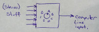
Audio source switch
with

I write this for two reasons, one is obviously to
log of a project, the other is to illustrate a problem that I think
that all makers come up against, with a sprinkling of some new and old
tricks I'v learned.
The project: Well you can scroll down and glimpse at
the images to understand what I built, I needed an audio source
selector for my computer, as I use a boosted mic system for online
chatting (line level output), I have a reel to reel tape player I'm
using to convert some media for a museum, etc etc. Just use a rotary
switch? Naaa, there would be switching noise, that and dealing with
contacts that seem to (almost regardless of the switch quality)
evenuallty go all funny and make bad connections etc. This is where
part 2 of this article comes in.
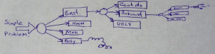
The maker problem: Its funny really, when you
start out making things, you don't know how to do anything, so you
learn a way, then implement it, thing built. Might not be the best
functioning in the world, but it works, fix it as required, put up with
the occasional bit of attitude. Then, as time goes on, you learn more
and more ways to do the same things, good right? no... Suddenly you
find yourself with what is, and you know it, a simple project, but for
some reason you find that you have been sitting for days designing it.
One of my three featured things in this article is the power supply, so
I'll follow my example with that. So at this point the problem has
already begun, you need an audio switch, and have already decided that
a rotary switch, tho simple, is flawed, poor quality, you can do
better. For an electronic switch, you need a power supply, back in the
day, you would take an ac output transformer, recify, filter, and
regulate its output, bam!, power supply. Its 2012 tho, magnetic
transformers are passe, switching power supplies are where its at,
smaller, lighter, more efficient... see where this is going? Every step
of the project you are passing up 'inferior' options, I have seen some
people forgo building their projects at all because the worlds
technology is just not up to snuff for them, they never end up building
anything since that first transistor led flasher (which of course is no
way to flash an LED right? everyone knows you use a 555 tiny13 arduino rasberry pi)
Its enough to turn even Cinderella into a troll.
My words are: JUST BUILD IT. Use the advice you would give a novice who
would only be able to do a simple solution. You will notice I also
didn't use a drafting program for all the diagrams!
Lets go:
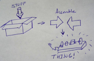
I keep a lot of stuff that could come in handy one day. Another side to
the maker problem is the "Thats too good to use for THIS project"...
Just use it. (NEVER save microcontrollers for a special project later.)
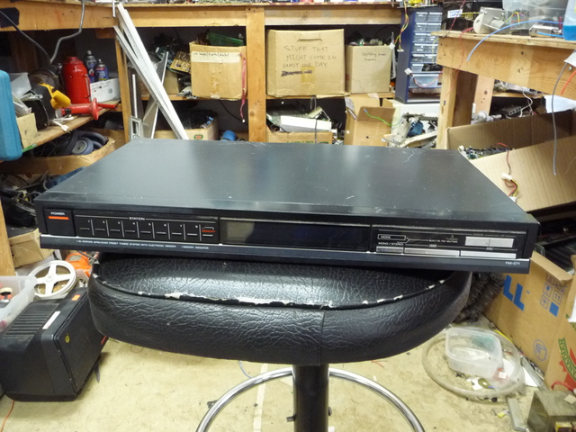
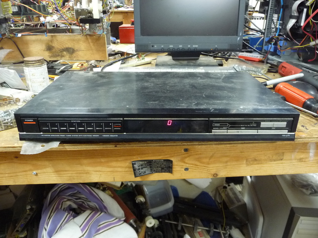
This starts with a ~1U radio I couldn't bare to get rid of, cause it had buttons and a screen. (those are good features for a project, right?)
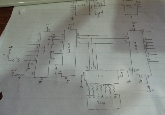
8 buttons, that works, I have some 4051 (8:1 bilarteral switch) chips I
been burning to use for SOMETHING. So, next step, design the core. I
want to have the buttons select the audio source, and the 4051 takes in
3 bit binary, so I need an encoder, which is handy, cause the led
driver chips also take binary. After listing all the chips that do
encoding, and all the chips that drive displays, I find enough
'junkbox' stuff to make it work. A 4532 for the encoding, and a 7447
for the display. But wait, why not use a microcontroller? their too
valuable for this project, and I'd have to write a bunch of code....
7447, the paper says 4511, here again, as it turns out, all the
displays I have are common anode, I can get away with a TTL chip for a
few reasons, its got the same pinout as the 4511, and its only taking
input from the cmos (so the logic levels are ok). This also requires
poking in a latch to hold the converted binary result, sticking with
cmos, a 4042 works....ok.... (see? just 3 chips to replace the
microcontroller!)
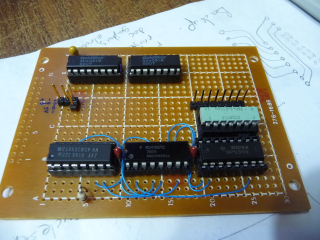
Building the circuits:
Well now, I have an etching setup,
but this is a one-off project and I can build this on veroboard pretty
quick, so, thats the plan. One of the great things about verobaord is
that circuits tend to be smaller, being that the number of effective
PCB layers of jumpers is almost unlimited. I was given a pile of
veroboard once from an estate cleanout, I regard them as really
valuable, **but not so much that I must never use them**. I have
two boards here, a controller board, with the logic chips, audio
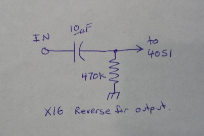
switches and some spare space, and a board for DC rejection, another
one of those "I know too much" things, see, the power supply I plan for
this is +- 5V (stupid analog stuff and its need for negitive power
supplies) the audio is about 1Vp-p, if there was a dc bias of the
incomming audio over a volt of so, the switch would screw up, cant have
that. The DC blocking is done with a high pass filter, 10uF and 470k
ohms, the pole on that filter is so low that it really wont effect
audio quality. (I could center the audio to 2.5V, but this wouldn't
leave as much headroom as I'm comfortable with.
Controller board:
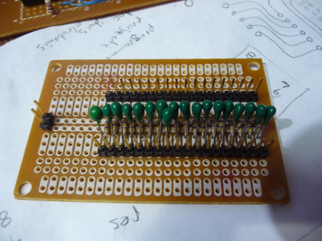
DC blocking (16 input and 2 output channels):
If your thinking that the control board wiring looks odd, (sorry, I
didn't take a pic of the bottom) What I do is use the power carrier
traces on the protoboardfor the power, solder in standard chip
sockets, then for the point to point stuff, I use wire wrap wire that
goes thru the adjacent hole, then folds over into the solder pool
holding the socket on. (which gets trickey if you try to take 5 lines
off 1 pin)
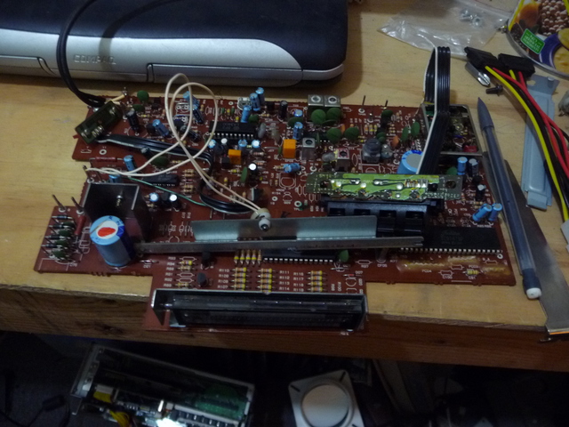
Out come the guts of the radio, there is a nice VFD screen there, but I
dont want to have to drive it, even tho there is a generic driver chip
ON it, and I know how to make drivers, and how to operate it. The VFD
can go in the "goodies" box.
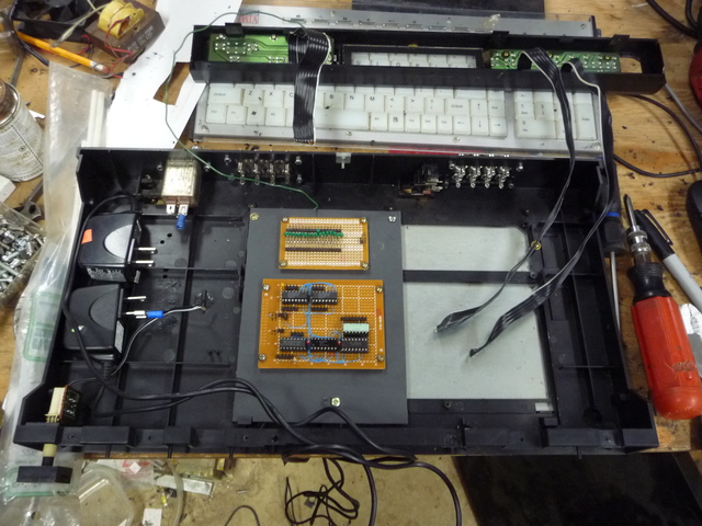
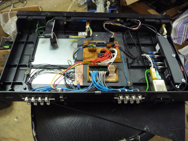
Next, regutting the radio. Here is the start of three featured tricks I wanted to show you.
a) I have decided to phase out linear supplies on my projects,
switching supplies are getting so available and easy to use. I did
start off this project by going thru all the switching power
supply pcbs that I'v put aside, most of them were just too tall for
this project. I collect 5V cell phone charger adapters, you can usually
get them at a thriftstore for between $0.25 and $1 ea, they are
regulated 5V, between 100mA and 1A, I think thats a pretty good price
for a ~5W adapter. I'v been telling myself that these adapters are
prettymuch capable to feed about any of the projects I come up with,
lets prove it.
+- 5V, ok, in goes 2 adapters.
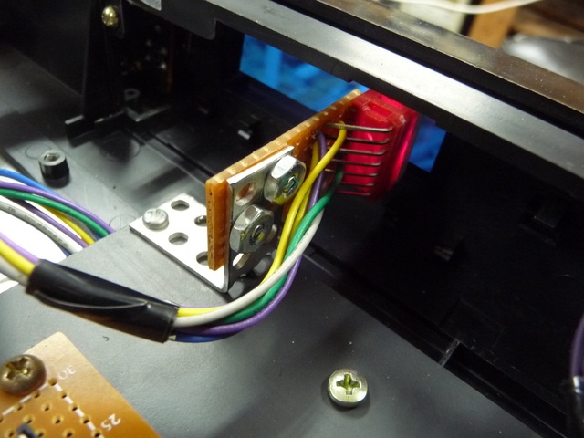
b) Funny thing, did you know 1/4" spade connectors perfectly fit North
American plug prongs? (well if they aren't keyed) Thats what I call
just plain handy, I don't even need to break UL (CSA) on these little
guys, just throw them in!
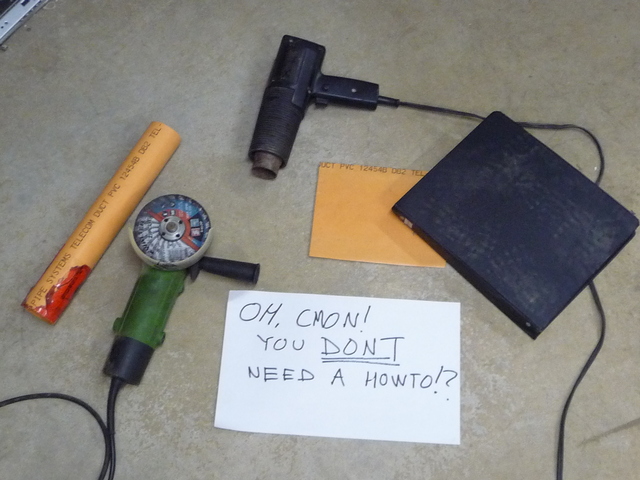
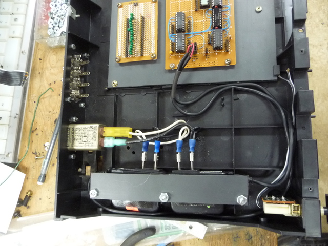
c) See that nice grey plastic plate I mounted the circuit boards to?
Well its cheap and REALLY available. Its commonly found in white, but
can be obtained in grey and orange.
(hint: its pvc pipe, slit lengthwise, heat, and flatten.)
Remember the best images are taken on a newly cleaned floor.
Everything should be nice and secure, so I strapped the adapters down,
with some doublesided tape to discourage slipping. (so much for heat
dissipation). Notice I didn't fuse it, the adpaters are already CSA...
yes, I should use fully insulated spades, but apparently the shop is
out of them (I had to dig hard just to find those)
Mountng the display was an interesting excersize, I found a 90degree
socket I pulled off something, which was, with a little bending and
spacing, perfect. my only common cathode displays were too large for
the front window, hence me using the 74ls47 to drive it.
Finished new guts. Note the spring off the ground "bar" that grounds the top lid.
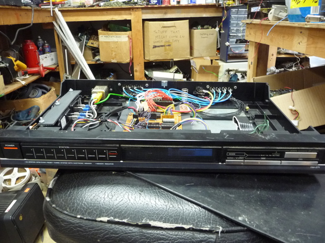
All said and done, boxed back up, dosn't look half bad. Interesting
note tho, the first button is labeled 1, the last 8. 3 bit priority
encoder, so it outputs 0-7.
I suppose I have to blame any confusion on why button 2 brings up
channel 1 on a man/machine interpertation error. It should be obvious
that the first channel is channel 0. Yes, I could fix it with a 3 input
Nor gate and a re-arrangement of my channel order, not gonna bother.
(its hard writing for critics) Maybe one day later I can use the tuning
up/down buttons for volume level, and I could add some led bar graph VU
meters, and....
One of the nice features, is that, because its a passive audio switch, it can do 8:1 or 1:8.
OOPS:
You will notice I really carefully grounded the inputs to the power
ground, had to disconnect that, it seems that the house ground has all
sorts of noise on it, which entered the audio in some rather odd ways.
But, is it a hack?