Vacume Flourescent Display (VFD)
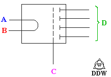
 Here is what the symbol for the little fellows looks like, I'm sorta assuming that you can get the pinout of whatever display you are using, its not too hard to figure out either.
A and B are filiment connections, C is grid and D is anode.
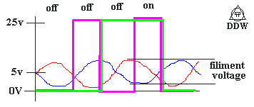
 Here is the waveform that is required...
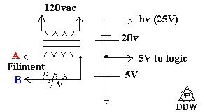
The amount of filiment voltage varies with the display kind, the one in a vcr that i reverse engineered used about 8Vp-p, a smaller display used 4Vp-p, if a transformer of the right voltage isn't on hand a resistor (dotted in) can be used.
If you have just pulled a display out of something (like a vcr) and dont know what voltage you need for the filiment, then you might try using a variable resistor, if the filiment can be seen glowing, turn it down. I found that the display worked at quite a lot less power than it took to glow the filiment.
 Power supply, note that the battery symbols can be any power supply, if you wanted you could also use a power supply with a 5 and 25v output.
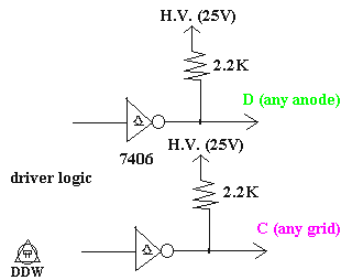
 And a driver cct.
Most of these displays that i have come across have been more then one digit, there also mutiplexed, making logic all the more fun.
There are no spelling erors in this, my room is declared as a seperete country in wich the rules of spelling are difrent. I do make mistakes, and if there is one in a schematic i have provided you have my permission to write me a mean letter. I take no responceability for those who take apart other people's vcr's to get the display, or if you burn out the filiment because the testing pot was turned to 0ohms when too much power was applied...
Back, need more be said?
 Rue Mohr, Member of planet earth (currently)
 Here is what the symbol for the little fellows looks like, I'm sorta assuming that you can get the pinout of whatever display you are using, its not too hard to figure out either.
 Here is the waveform that is required...
 Power supply, note that the battery symbols can be any power supply, if you wanted you could also use a power supply with a 5 and 25v output.
 And a driver cct.
 Rue Mohr, Member of planet earth (currently)