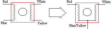
For the sake of playing with this I took a 2 phase stepper motor and commoned two of the wires to take the place of the motor for me, I wired it as follows:
The motor that I used was a disk drive stepper, 12v, 1.8 deg's/step,
.08A {block motor} using my trusty scope I found that I 5 uF capacitor
gave the desired 90 deg's of phase shift required.
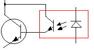
I took to reverse engineering a motor controller from the local pulp mill,
the first thing that interested me was a darlington arrangment used with
the opto isolators, thusly:
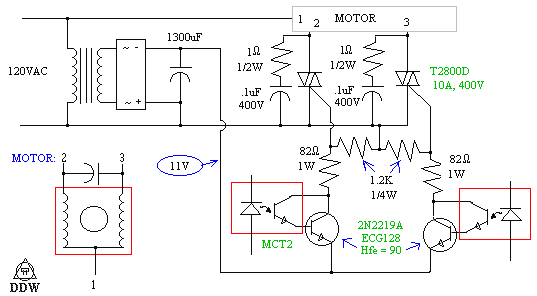
Here is the schematic from the reverse engineered controller, I'v left
out the other controll circuitry:
the controller was a [Jordan Controlls Inc 50-C-019338 REV 1]
And finally the circuit that I put togethor:
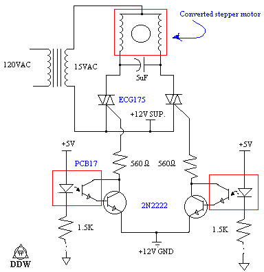
There are a few notes about doing this with 120V or higher motors..
* I have left out the snubbers, at this voltage and current there isn't
going to be any problems with power spikes killing the triacs
* I have left out a protecting resistor that should go in series with the
5 uF capicator, this protects the triacs from discharge currents if both
triacs are turned on.
A note for triggering triacs:
for calculating the gate resistor, use the following formulaeulas:
R = V/100mA where V is the source for triggering the triac.
P = V^2/R as you might quickly note, its desirable to have a low driving
voltage...
There are no spelling erors in this, my room is declared
as a seperete country in wich the rules of spelling are difrent. I don't
take responceability for you getting in trouble for taking apart other
peoples computers for partz. I do make mistakes, and if there is one in
a schematic i have provided you have my permission to write me a mean letter.
Back, need more be said?
![]()