
BabyBoard III
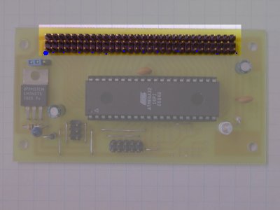
This is the "System 6" Power connecotor, and its pinout. The "+5V" can varry from 2V to 5V, the "+12V" can varry from 3.7V to 15V the marked values are typical. There is a 5V regulator that will generate the 5V from the "+12V" providing its given at least 7.5V. If you already have a 5V source, you can attach it directly to the 5V pins. Note that as a 6 pin connector, this can be plugged in without regard to its direction.


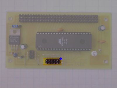
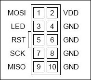
The programming connector on this is a standard 10 pin Atmel ISP port. The blue mark indicates pin 1.
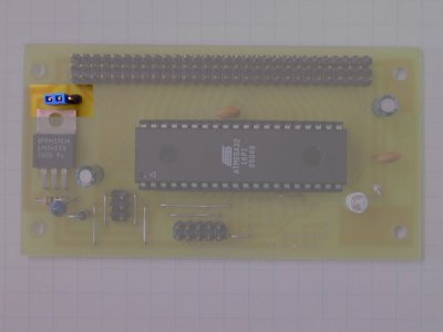
The power jumper determines the voltage on the I/O power bus. This is selectable between teh 5V bus and the Bulk power bus ("+12V") The left side selects 5V, and the right side selects bulk power. (The position in the picture is 5V).
| Row |
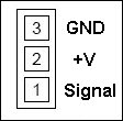
Column 1 Signal |
Column 2 Signal | Column 3 Signal |
| 1 |
PB0 |
+5V |
Ground |
| 2 |
PB1 |
+5V |
Ground |
| 3 |
PB2 |
+5V |
Ground |
| 4 |
PB3 (PWM 0 ) |
+5V |
Ground |
| 5 |
PB4 |
+5V |
Ground |
| 6 |
PB5 |
+5V |
Ground |
| 7 |
PB6 |
+5V |
Ground |
| 8 |
PB7 |
+5V |
Ground |
| 9 |
PA0 (ADC0) |
+5V |
Ground |
| 10 |
PA1 (ADC1) | +5V | Ground |
| 11 |
PA2 (ADC2) | +5V | Ground |
| 12 |
PA3 (ADC3) | +5V | Ground |
| 13 |
PA4 (ADC4) | +5V | Ground |
| 14 |
PA5 (ADC5) | +5V | Ground |
| 15 |
PA6 (ADC6) | +5V | Ground |
| 16 |
PA7 (ADC7) | +5V | Ground |
| 17 |
PC7 |
+5V | Ground |
| 18 |
PC6 |
+5V | Ground |
| 19 |
PC5 |
+5V | Ground |
| 20 |
PC4 |
+5V |
Ground |
| 21 |
PC3 |
+5V | Ground |
| 22 |
PC2 |
+5V | Ground |
| 23 |
PC1 |
+5V | Ground |
| 24 |
PC0 |
+5V | Ground |
| 25 |
PD7 (PWM 1) |
+5V | Ground |
| 26 |
PD2 |
+5V | Ground |
| 27 |
PD3 |
+5V | Ground |
| 28 |
PD4 |
+5V | Ground |
| 29 |
PD5 |
+5V | Ground |
| 30 |
PD6 |
+5V | Ground |